Department of Computer Science
CSU Stanislaus
California State University
Computer Architecture
Simulators for Different Instruction Formats
Xuejun Liang
Fall 2020
Introduction
Assembly language programming and writing, using and modifying processor simulators are major hands-on assignment categories in an undergraduate computer architecture course. There are many computer architectures with different instruction formats such as stack-based, accumulator-based, two-address, or three-address machine. But, in general, only one architecture will be chosen for teaching assembly language programming in a computer architecture class or textbook. It is certainly desirable to have various simple simulators, each for one major computer processor architecture, so that students can program and compare these processors.
To this end, seven simple computer architecture simulators are designed and implemented for different instruction formats, including stack-based, accumulator-based, two-address (2A), and three-address (3A) machines. Both memory-to-memory (M2M) and register-to-register (R2R) architectures are implemented for both 2A and 3A machines. In addition, memory-to-register (M2R) architecture is implemented for 2A machine. These simulators can be used to assemble and run assembly language programs on these simulated computer architectures. Several simple applications are used to illustrate how to develop assembly language programs to deal with arithmetic expressions, arrays, loops, stacks, subroutines, and recursions on these computer architectures.
Students will have a better understanding of computer architectures by using these simulators for their assembly language programming exercises. Students can also modify these simulators to add more instructions, debugging functions, and etc. In addition, these simulated machines can serve as the compiler’s target machines for the code generation practice.
My Papers and Presentations about These
Simulators
Paper: Computer Architecture Simulators for Different Instruction Formats
Presentation: Computer Architecture Simulators for Different Instruction Formats
Paper: More on Computer Architecture Simulators for Different Instruction Formats
Presentation: More on
Computer Architecture Simulators for Different Instruction Formats
Assembly
Language Program Structure, Syntax, and Examples
Any assembly language program
of all simulated machines consists of three parts: data section (optional),
code section, and input section (optional) separated by a key word END.
The data section is
used for declaring variables in memory. Each declaration takes one line and consists
of ID, Type, and Value. ID is a variable name, Type indicates number of words
the variable value has, and Value is optional initial value(s) of the variable.
The code section consists of assembly language instructions. Each instruction
takes one line and precedes an optional label immediately followed by ‘:’
symbol. The input section is used for providing user input data. One line
contains only one word (integer). In addition, users can add comments starting
from // symbol and until to the end of line. A comment cannot cross multiple
lines.
Example 1: Add two integers and print the sum on the screen
using accumulator machine.
|
//Program A //Declaration Num1 1 //Variable holding the first number Num2 1 //Variable holding the second number Sum 1 //Variable the sum END //Code READ //Read the first number, AC = 23 PUT
Num1 //Store the first number in Num1 READ //Read the second number, AC = 48 PUT
Num2 //Store the second number in
Num2 ADD
Num1 //Add the first number, AC =
48+23 PUT
Sum //Store sum at address Sum PRNT //Print the Sum STOP //Terminate program END //User input 23 //The
first number to add 48 //The
first number to add
|
//Program B //Declaration Num1 1 23 //The
first number to add Num2 1 48 //The
second number to add Sum 1 //The sum END //Code GET
Num1 //Get the first number, AC = 23 ADD
Num2 //Add the second number, AC =
23+48 PUT
Sum //Store sum at address Sum PRNT //Print the Sum STOP //Terminate program END //No user input
|
Both
programs are adding two integers and print the sum on the screen. Program A
defines three initialized variables Num1, Num2 and Sum in the declaration
section and have two integers specified in the input section, while Program B
defines two initialized variables Num1 and Num2 and one initialized variable
Sum n the declaration section and has no user inputs in the input section. In
the code section, Program A reads integers from user input, while Program B
gets integers from memory. Finally, they print the sum on the screen.
Example 2: Compute Z = (X+Y)*(W-Y) and print
Z, where X, Y, and W are three initialized variables and Z is an uninitialized
variable.
·
Stack machine code (expr_0a)
·
Accumulator code (expr_1a)
·
Two-address memory-to-memory code (expr_2a_m2m)
·
Two-address memory-to-register code (expr_2a_m2r)
·
Two-address register-to-register code (expr_2a_r2r)
·
Three-address memory-to-memory code (expr_3a_m2m)
·
Three-address register-to-register code (expr_3a_r2r)
Example 3: Compute the sum of absolute
values of elements in an array, where the array and its length are initialized
in the data section. The sum will be stored in memory and displayed on screen.
·
Stack machine code (sum_array_0a)
·
Accumulator code (sum_array_1a)
·
Two-address memory-to-memory code (sum_array_2a_m2m)
·
Two-address memory-to-register code (sum_array_2a_m2r)
·
Two-address register-to-register code (sum_array_2a_r2r)
·
Three-address memory-to-memory code (sum_array_3a_m2m)
·
Three-address register-to-register code (sum_array_3a_r2r)
Simulator Jar
Files (Executable)
·
Stack machine (StackMachine.jar)
·
Accumulator (Accumulator.jar)
·
Two-address memory-to-memory (TwoAm2m.jar)
·
Two-address memory-to-register (TwoAm2r.jar)
·
Two-address register-to-register (TwoAr2r.jar)
·
Three-address memory-to-memory (ThreeAm2m.jar)
·
Three-address register-to-register (ThreeAr2r.jar)
Simulator
Source Files
·
Stack machine (ZeroAddress.java)
·
Accumulator (OneAddress.java)
·
Two-address memory-to-memory (TwoAddressM2M.java)
·
Two-address memory-to-register (TwoAddressM2R.java)
·
Two-address register-to-register
(TwoAddressR2R.java)
·
Three-address memory-to-memory
(ThreeAddressM2M.java)
·
Three-address register-to-register (ThreeAddressR2R16.java)
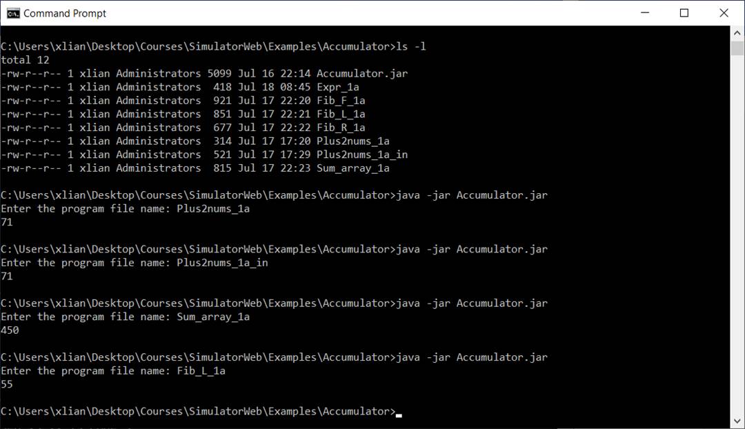
How to Use
Simulators
All simulators will be
used in the same way. You should use different folds for different simulated
machines. The accumulator is used as an example in the following steps.
1. Download the simulator Accumulator.jar and save it in
a folder, for example, C:\Courses\CS3740\Simulators\Accumulator.
2. Download example programs for the
accumulator machine: Plus2nums_1a,
Expr_1a, Sum_array_1a, etc. and save them
in the same folder.
3. Run the simulator with Microsoft
Windows
a. Open a Command
Prompt window by running cmd
b. Change current
directory to the folder which contains Accumulator.jar file and your program
files and type
java
-jar Accumulator.jar
c. Entering your
assembly source code file name following the simulator’s prompt.
Important Note:
The simulators have a
very limited ability to report error messages. So, please follow the syntax
carefully. A syntax error could cause the simulators to crash. Most common
mistakes are misspellings of instructions, variables, or labels. Please note
all the instructions are upcasted.
Programming
Assignments
The programming assignments
will include writing assembly language programs to evaluate arithmetic
expressions, to deal with arrays, stacks, and functions by using these
simulators, and adding instructions and pseudo-instructions by modifying these
simulators.
PA 1: Evaluate Arithmetic
Expression
Please compute the
following arithmetic expression, save the result in the memory,
W = (X+Z)*Y + X*Z +
X*Y*Z - X + Y - Z
and display the result on
the screen. Assume that the initial value X = 24, Y = -8, and Z = -13.
You can use the
following skeleton programs to star your coding.
·
Stack machine skeleton code (ExprPA1_0a)
·
Accumulator skeleton code (ExprPA1_1a)
·
Two-address memory-to-memory skeleton code (ExprPA1_2a_m2m)
·
Two-address memory-to-register skeleton code (ExprPA1_2a_m2r)
·
Two-address register-to-register skeleton code (ExprPA1_2a_r2r)
·
Three-address memory-to-memory skeleton code (ExprPA1_3a_m2m)
·
Three-address register-to-register skeleton code (ExprPA1_3a_r2r)
Instruction
Sets of Simulated Machines
In simulated machines,
all data are 32 bits and all addresses and immediate data are 16 bits. All
instructions in one simulated machine are of the fixed word length which may be
different for different machines.
The notation M[A]
represents the memory content at memory address A. The acronym Imm stands for 16-bit immediate number, PC
for program counter, SP for stack pointer, FP for frame pointer,
and AC for accumulator.
In all simulated machines,
stack will grow towards higher memory address. SP and FP are
registers in stack-based, and two-address register-to-register and
memory-to-register, and three-address register-to-register machines, while SP
is a reserved memory location and FP is not available in
accumulator-based, two-address memory-to-memory, and three-address
memory-to-memory machines.
It is assumed that
there are 32 general purpose registers available in simulated memory-to-register
and register-to-register architectures. The register usage will follow the MIPS
convention as shown below.
|
Name |
Number |
Usage |
|
$zero |
$0 |
The constant value 0 |
|
$at |
$1 |
Reserved for assembler |
|
$v0-$v1 |
$2-$3 |
Expression evaluation
and results of a function |
|
$a0-$a3 |
$4-$7 |
Argument 1-4 |
|
$t0-$t7 |
$8-$15 |
Temporary (not preserved
across call) |
|
$s0-$s7 |
$16-$23 |
Saved temporary
(preserved across call) |
|
$t8-$t9 |
$24-$25 |
Temporary (not preserved
across call) |
|
$k0-$k1 |
$26-$27 |
Reserved for OS kernel |
|
$gp |
$28 |
Pointer to global area |
|
$sp |
$29 |
Stack pointer |
|
$fp |
$30 |
Frame pointer |
|
$ra |
$31 |
Return address (used by
function call) |
Seven Instruction sets
for simulated machines are listed below for your reference. Pseudo-instructions
are not listed here. Please read my papers and presentations for details.
A. Stack-Based (Zero-Address) Instruction Set
|
op |
Instruction |
Explanation |
|
0 |
ADD |
Pop the top two addends,
add, and push the sum |
|
1 |
SUB |
Pop the subtrahend and
minuend, subtract, and push the difference |
|
2 |
MUL |
Pop the multiplicand and
multiplier, multiply, and push the product |
|
3 |
DIV |
Pop the dividend and
divisor, divide, and push the quotient |
|
4 |
REM |
Pop the dividend and
divisor, divide, and push the remainder |
|
5 |
GOTO Label |
Unconditionally jump to
the instruction at address Label |
|
6 |
BEQZ Label |
Pop the top item and
jump to Label if the popped item is zero |
|
7 |
BNEZ Label |
Pop the top item and
jump to Label if the popped item is not zero |
|
8 |
BGEZ Label |
Pop the top item and
jump to Label if the popped item is greater than or equal to 0 |
|
9 |
BLTZ Label |
Pop the top item and
jump to Label if the popped item is less than 0 |
|
10 |
JNS Label |
Push the return address
and transfer the control to the instruction at address Label |
|
11 |
JR nLoc |
Pop the return address
into PC and decrement SP by nLoc |
|
12 |
PUSH FP |
Push the content of FP
on stack |
|
13 |
PUSH FP+Imm |
Push M[FP+Imm] on stack |
|
14 |
PUSH Imm |
Push a 16-bit integer
value Imm on stack |
|
15 |
PUSH Var |
Push M[Var] on stack |
|
16 |
PUSHI Var |
Push M[M[Var]] on stack |
|
17 |
POP FP |
Pop the top item into FP
from stack |
|
18 |
POP FP+Imm |
Pop the top item into M[FP+Imm] from stack |
|
19 |
POP Var |
Pop the top item into
M[Var] from stack |
|
20 |
POPI Var |
Pop the top item into
M[M[Var]] from stack |
|
21 |
SWAP |
Swaps the top two items
on the stack |
|
22 |
MOVE |
Copy content of SP
into FP |
|
23 |
ISP nLoc |
Increase/decrease SP
by nLoc |
|
24 |
READ |
Read an input and push
it on stack |
|
25 |
PRNT |
Print the top item on
stack |
|
26 |
STOP |
Terminate the program |
B. Accumulator-Based (One-Address) Instruction
Set
|
Op |
Instruction |
Meaning |
|
0 |
LI Imm LA Var |
AC ß Imm AC ß address
of Var |
|
1 |
ADDI Imm |
AC ß AC+Imm |
|
2 |
ADD Var |
AC ß
AC+M[Var] |
|
3 |
SUB Var |
AC ß
AC-M[Var] |
|
4 |
MUL Var |
AC ß
AC*M[Var] |
|
5 |
DIV Var |
AC ß
AC/M[Var] |
|
6 |
REM Var |
AC ß
AC%M[Var] |
|
7 |
GET Var |
AC ß M[Var] |
|
8 |
PUT Var |
M[Var] ß AC |
|
9 |
GOTO Label |
PC ß
Label |
|
10 |
BEQZ Label |
If AC = 0 then PC
ß
Label |
|
11 |
BNEZ Label |
If AC |
|
12 |
BGEZ Label |
If AC |
|
13 |
BLTZ Label |
If AC < 0 then
PC ß Label |
|
14 |
JNS Label |
Push the return address
and PC ß Label |
|
15 |
JR |
Pop the return address
into PC |
|
16 |
READ |
Read an input and save
it to AC |
|
17 |
PRNT |
Print AC |
|
18 |
STOP |
Terminate the program |
|
19 |
GETI Var |
AC ß
M[M[Var]] |
|
20 |
PUTI Var |
M[M[Var]] ß AC |
C. Two-Address Memory-to-Memory Instruction
Set (2A M2M)
|
|
Instruction |
Meaning |
|
0 |
LI A
Imm LA A Var |
M[A] ß Imm M[A] ß
address of Var |
|
1 |
ADDI A Imm |
M[A] ß
M[A]+Imm |
|
2 |
ADD A
B |
M[A] ß
M[A]+M[B] |
|
3 |
SUB A
B |
M[A] ß M[A]-M[B] |
|
4 |
MUL A
B |
M[A] ß
M[A]*M[B] |
|
5 |
DIV A
B |
M[A] ß
M[A]/M[B] |
|
6 |
REM A
B |
M[A] ß
M[A]%M[B] |
|
7 |
GET A
B |
M[A] ß
M[M[B]] |
|
8 |
PUT A
B |
M[M[B]] ß
M[A] |
|
9 |
GOTO Label |
PC ß
Label |
|
10 |
BEQZ A
Label |
If M[A] = 0 GOTO Label |
|
11 |
BNEZ A
Label |
If M[A] |
|
12 |
BGEZ A
Label |
If M[ |
|
13 |
BLTZ A
Label |
If M[A] < 0 GOTO
Label |
|
14 |
JNS Label |
M[SP] = M[SP]+1,
M[M[SP]] = PC, & PC ß
Label |
|
15 |
JR |
PC ß
M[M[SP]] & M[SP] = M[SP]-1 |
|
16 |
READ |
M[INPUT] ß
Input |
|
17 |
PRNT |
Display M[OUTPUT]
on screen |
|
18 |
STOP |
Terminate program |
Where A and B are memory locations (variables).
D. Three-Address Memory-to-Memory Instruction
Set (3A M2M)
|
|
Instruction |
Meaning |
|
0 |
LI A
Imm LA A
Var |
M[A] ß Imm M[A] ß
address of Var |
|
1 |
ADDI A
C Imm
|
M[A] ß
M[C]+Imm |
|
2 |
ADD A
C B |
M[A] ß
M[C]+M[B] |
|
3 |
SUB A
C B |
M[A] ß
M[C]-M[B] |
|
4 |
MUL A
C B |
M[A] ß
M[C]*M[B] |
|
5 |
DIV A
C B |
M[A] ß
M[C]/M[B] |
|
6 |
REM A
C B |
M[A] ß
M[C]%M[B] |
|
7 |
GET A
C B |
M[A] ß
M[C+M[B]] |
|
8 |
PUT A
C B |
M[C+M[B]] ß
M[A] |
|
9 |
GOTO Label |
PC ß
Label |
|
10 |
BEQ A
C Label |
If M[A] = M[C]
GOTO Label |
|
11 |
BNE A
C Label |
If M[A] ≠ M[C] GOTO Label |
|
12 |
BGE A
C Label |
If M[A] ≥ M[C] GOTO Label |
|
13 |
BLT A
C Label |
If M[A] < M[C]
GOTO Label |
|
14 |
JNS Label |
M[SP] = M[SP]+1,
M[M[SP]] = PC, & PC ß
Label |
|
15 |
JR |
PC ß
M[M[SP]] & M[SP] = M[SP]-1 |
|
16 |
READ |
M[INPUT] ß
Input |
|
17 |
PRNT |
Display M[OUTPUT]
on screen |
|
18 |
STOP |
Terminate program |
Where A and B are memory locations (variables).
E. Two-Address Register-to-Register
Instruction Set (2A R2R)
|
|
Instruction |
Meaning |
|
0 |
LI R
Imm LA R
Var |
R ß Imm R ß
address of Var |
|
1 |
ADDI R Imm |
R ß
R+Imm |
|
2 |
ADD R
R1 |
R ß
R+R1 |
|
3 |
SUB R
R1 |
R ß
R-/R1 |
|
4 |
MUL R
R1 |
R ß
R*R1 |
|
5 |
DIV R
R1 |
R ß
R/R1 |
|
6 |
REM R
R1 |
R ß
R%R1 |
|
7 |
GET R
R1 |
R ß
M[R1] |
|
8 |
PUT R
R1 |
M[R1] ß
R |
|
9 |
GOTO Label |
PC ß
Label |
|
10 |
BEQZ R
Label |
If R = 0 GOTO Label |
|
11 |
BNEZ R
Label |
If R |
|
12 |
BGEZ R
Label |
If R |
|
13 |
BLTZ R
Label |
If R < 0 GOTO Label |
|
14 |
JNS Label |
$ra ß
PC & PC ß Label |
|
15 |
JR |
PC ß
$ra |
|
16 |
READ |
$v0 ß
Input |
|
17 |
PRNT |
Print $a0 |
|
18 |
STOP |
Terminate program |
Where R and R1 are registers.
F. Two-Address Memory-to-Register Instruction
Set (2A M2R)
|
|
Instruction |
Meaning |
|
0 |
LI R
Imm LA R
Var |
R ß Imm R ß
address of Var |
|
1 |
ADDI R Imm |
R ß
R+ Imm |
|
2 |
ADD R
A/R1 |
R ß
R+M[A]/R1 |
|
3 |
SUB R
A/R1 |
R ß
R-M[A]/R1 |
|
4 |
MUL R
A/R1 |
R ß
R*M[A]/R1 |
|
5 |
DIV R
A/R1 |
R ß
R/M[A]/R1 |
|
6 |
REM R
A/R1 |
R ß
R%M[A]/R1 |
|
7 |
GET R
A/R1 |
R ß
M[A/R1] |
|
8 |
PUT R
A/R1 |
M[A/R1] ß
R |
|
9 |
GOTO Label |
PC ß
Label |
|
10 |
BEQZ R Label |
If R = 0 GOTO Label |
|
11 |
BNEZ R
Label |
If R |
|
12 |
BGEZ R
Label |
If R |
|
13 |
BLTZ R
Label |
If R < 0 GOTO Label |
|
14 |
JNS Label |
$ra ß
PC & PC ß Label |
|
15 |
JR |
PC ß
$ra |
|
16 |
READ |
$v0 ß
Input |
|
17 |
PRNT |
Print $a0 |
|
18 |
STOP |
Terminate program |
Where R and R1 are registers and
A is a memory location.
G. Three-Address Register-to-Register
Instruction Set (3A R2R)
|
op |
Instruction |
Meaning |
|
0 |
LI R Imm
LA R
Var |
R ß Imm R ß address
of Var |
|
1 |
ADDI R R1 Imm |
R ß
R1+Imm |
|
2 |
ADD R R1 R2 |
R = R1 + R2 |
|
3 |
SUB R R1 R2 |
R = R1 + R2 |
|
4 |
MUL R R1 R2 |
R = R1 + R2 |
|
5 |
DIV R R1 R2 |
R = R1 + R2 |
|
6 |
REM R R1 R2 |
R = R1 + R2 |
|
7 |
GET R R1 offset |
R ß
M[R1+ offset] |
|
8 |
PUT R R1 offset |
M[R1+ offset] ß R |
|
9 |
GOTO L |
PC ß L |
|
10 |
BEQ R1 R2
Label |
If R1 = R2 GOTO Label |
|
11 |
BNE R1 R2
Label |
If R1 |
|
12 |
BGE R1 R2
Label |
If R1 |
|
13 |
BLT R1 R2
Label |
If R1 < R2 GOTO Label |
|
14 |
JNS Label |
$ra ß PC
& PC ß Label |
|
15 |
JR |
PC ß
$ra |
|
16 |
READ 0 0 0 |
$v0 ß
Input |
|
17 |
PRNT 0 0 0 |
Print $a0 |
|
18 |
STOP 0 0 0 |
Stop |