(rev. March 7, 2018)
Notes On Chapter Six
-- Information Sources and Signals
- 6.0 Study Guide
- Know the concepts of analog and digital signals.
- Know the concepts of periodic and aperiodic signals in media.
- Know about sine waves - understand frequency, amplitude, phase and wavelength
- Understand that period is the length of a cycle in a time versus amplitude
plot, but wavelength is the length of a cycle in a distance versus amplitude
plot.
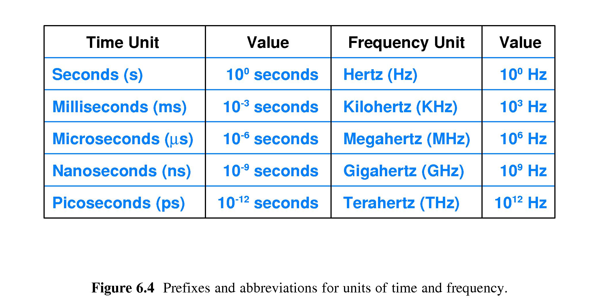
- Know what Hertz (Hz), Kilohertz (KHz), Megahertz (MHz), Gigahertz (GHz), and
Terahertz (THz) are.
- Understand what composite signals are.
- Understand what a plot of a signal in the frequency domain is.
- Understand what digital signals and signal levels are.
- Know what Baud rate is, what bit rate is, how they differ,
and how they are related (bps = [baud] * [floor(log2(levels))] ) .
- Understand the basics of how analog signals are converted to digital
signals, using sampling.
- Understand the Nyquist Theorem - sampling rate = 2 * fmax
- 6.1 Introduction
- 6.2 Information Sources
- Data communications relates to
arbitrary sources and destinations of
information, including devices other than computers.
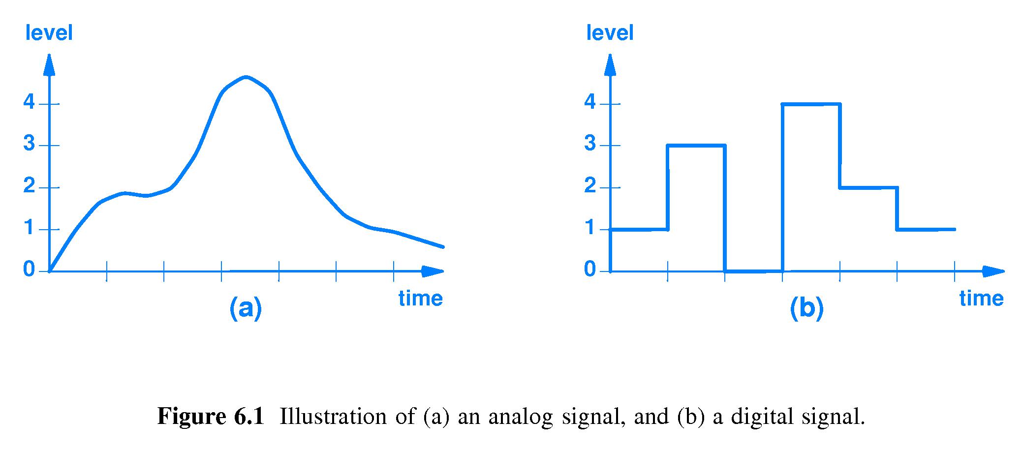
- 6.3 Analog and Digital Signals
-
Analog input or output moves through every value in between when it
changes from value X to value Y. A plot of an analog signal is a
continuous function - you have to keep your pencil on the paper as
you draw it.
-
Digital I/O jumps suddenly from value X to value Y when it changes.
A plot of digital I/O is like "stair steps".
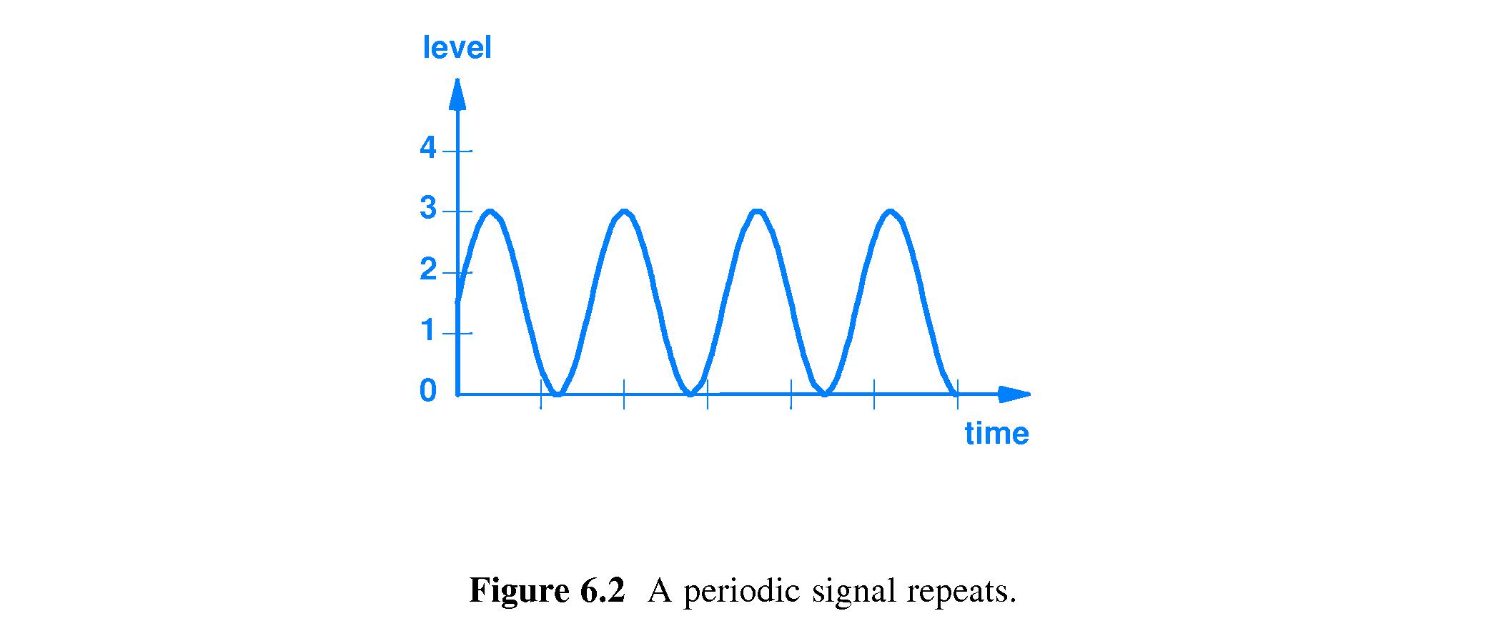
- 6.4 Periodic and Aperiodic Signals
-
Periodic analog or digital I/O
signals repeat the same pattern over
and over.
- Aperiodic signals don't
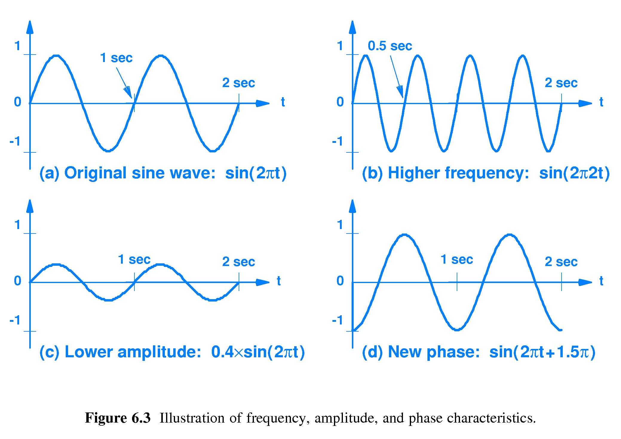
- 6.5 Sine Waves and Signal Characteristics
- 'Pure' audible tones are sinusoidal
- So is electromagnetic radiation
-
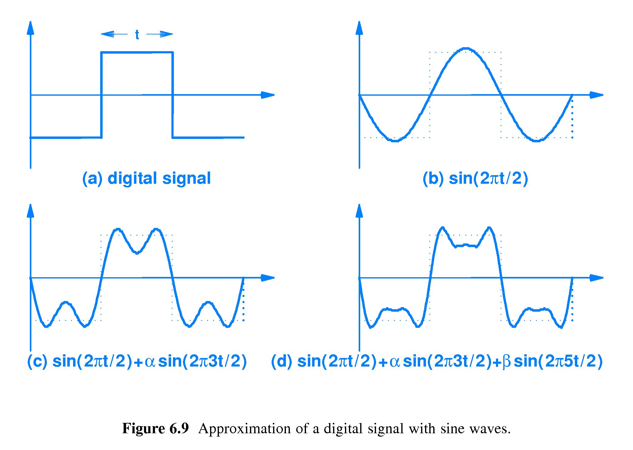
Basically, any periodic signal can be approximated well by a sum of
sinusoidal signals.
-
Important characteristics of sine waves:
- frequency
- amplitude
- phase
- wavelength
- Communication systems typically use high frequencies
- 6.6 Composite Signals
-
Composite signals are the sum of different sine waves
--
different frequencies, amplitudes and phases.
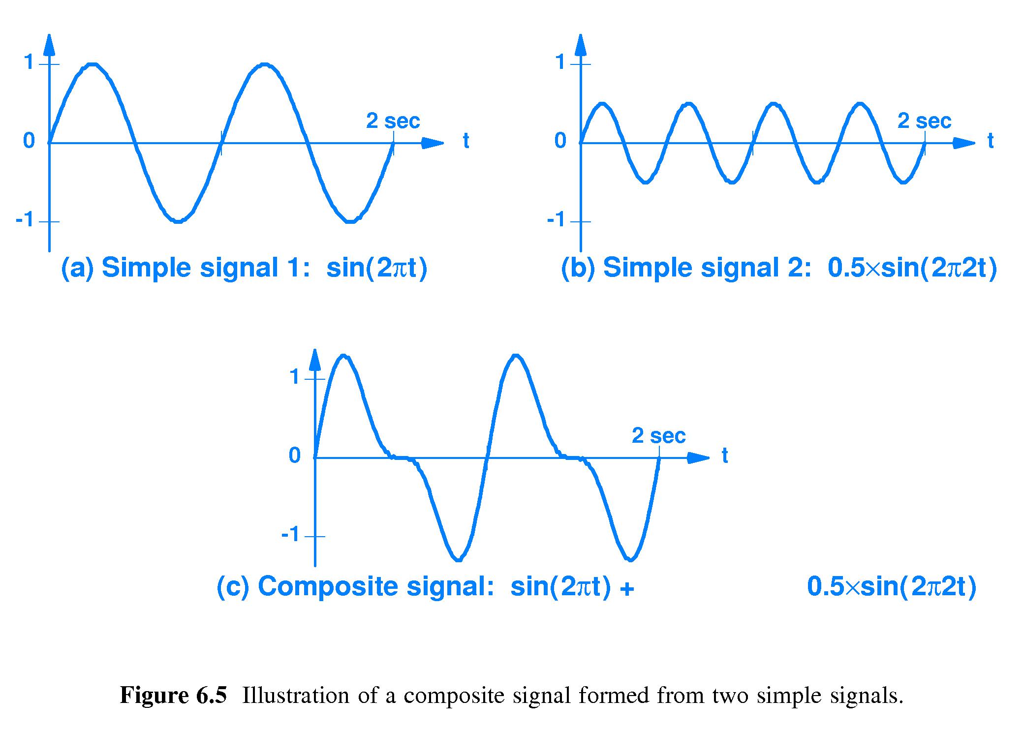
- 6.7 The Importance of Composite Signals and Sine Functions
- Modulated signals are typically composite
-
A sender's composite signal can be decomposed by the
receiver back into its pure sinusoidal constituent parts.
- The technique is Fourier transform - due to Joseph Fourier
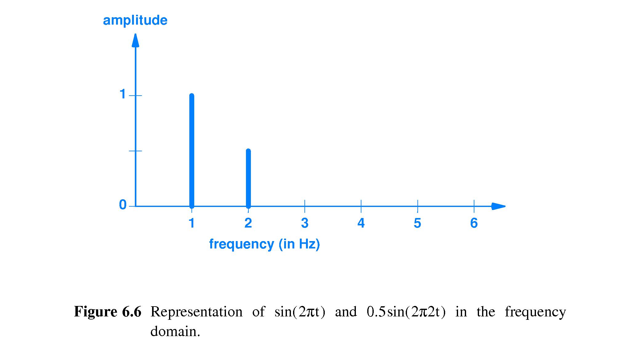
- 6.8 Time and Frequency Domain Representations
- Often it is convenient and informative to
represent a periodic signal
by plotting the set of points (f,A) for each constituent sinusoidal
signal of frequency f and amplitude A.
- It is a compact way to give a recipe for the construction of the signal.
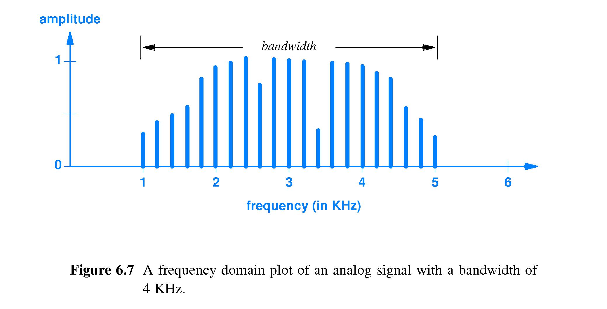
- 6.9 Bandwidth of an Analog Signal
-
The bandwidth of an analog signal is the difference between the
highest and lowest frequencies of the constituent parts.
- It is extremely simple to compute the bandwidth of a signal, given
a "plot in the frequency domain" -- a plot of frequency versus
amplitude.
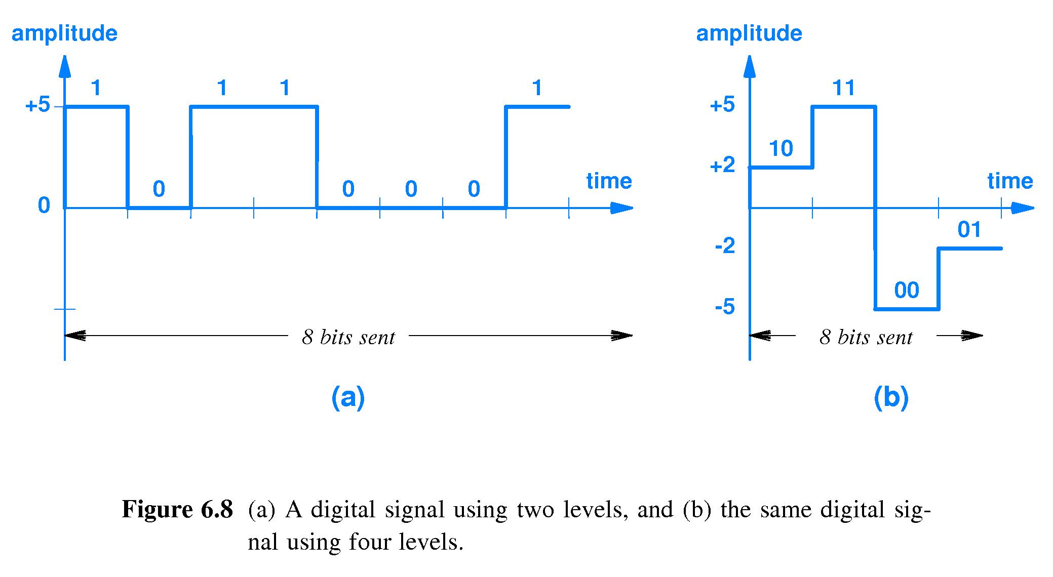
- 6.10 Digital Signals and Signal Levels
- If a digital signal output can change from one output level (e.g.
voltage) to another level during every interval of time T,
- and if the number of different output values to which the signal can
jump is 2N or more , then
- Then
every T seconds the signal can transmit a different one of the
2N possible combinations of N bits.
- In other words the signal can transmit N bits per time T.
- Example: If there are only two possible voltage levels then one level
can stand for "0" and the other can stand for "1" - the signal can
send one bit per unit of time T.
- Example: If there are four possible voltage levels then they can
stand for "00", "01", "10" and "11". Each time the signal jumps to a
new voltage it can be interpreted as another two-bit sequence. Thus
the signal can send two bits per unit of time T.
-
It would be nice if we had unlimited ability to speed up
communication by producing signals with more and more possible
output levels.
- There is a limit to how precisely a device can generate a desired
output level on a communication medium, and a limit to how well
a receiver can discriminate between two output levels that differ
only very slightly.
- Therefore, practical systems don't output very many different levels.
- 6.11 Baud and Bits Per Second
- Theoretically you can send more bits per second by increasing the
rate at which you change the signal output.
-
There's always going to be a limit to how fast than can be done (the
baud rate), and also a limit to how quickly the receiver will be able
to detect the changes. (
"Baud" is named after Émile Baudot.)
- The bit rate is determined by the baud rate and the number of output
levels:
- If there are 2N output levels possible, and
- the baud rate (#times level can change per second) is R, then
- the signal can transmit at a rate of RN bits per second.
- In short,
bps = (baud rate) X ( log2(#levels) ).
- 6.12 Converting a Digital Signal to Analog
-
Q: How do engineers convert digital signals to analog?
A: They approximate, using a composite of a few sine waves.
- 6.13 The Bandwidth of a Digital Signal
- According to the (technical) definition of bandwidth above,
a digital signal has infinite bandwidth, because
its frequency domain plot
"just keeps going out to infinity." In other words, you have to
an infinite range of frequencies to make a digital signal out of a
sum of sin waves.
- 6.14 Synchronization and Agreement about Signals
- Senders send, for example, by placing a level of a signal on a medium
for a certain interval of time T,
then a new level for the next interval of length T, and so on.
- In such a case, receivers receive by attempting to detect the levels
present on the media during each interval of length T.
-
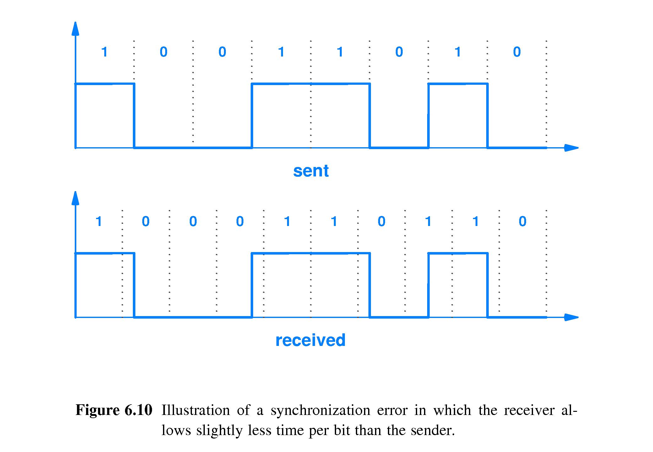
If the receiver is not in sync with the sender, errors can result -
for example if the sender sends 1001 and the receiver "samples" the
media too frequently, it might perceive each single bit as two bits -
so the 1001 that was sent could be received as 11000011.
- The error can be more subtle, as in the example where the sender sends 10011010
and the receiver sees it as 1000110110 - because its slightly fast sampling
rate makes the first two 0s seem like three, and makes the last 1 sent look
like two.
- How do we prevent such errors?
- 6.15 Line Coding
-
"Line Coding Techniques" may be utilized to solve synchronization
problems such as the ones described above.
- Actual line coding techniques in use are many and varied - details
beyond the scope of this text (see page 105).
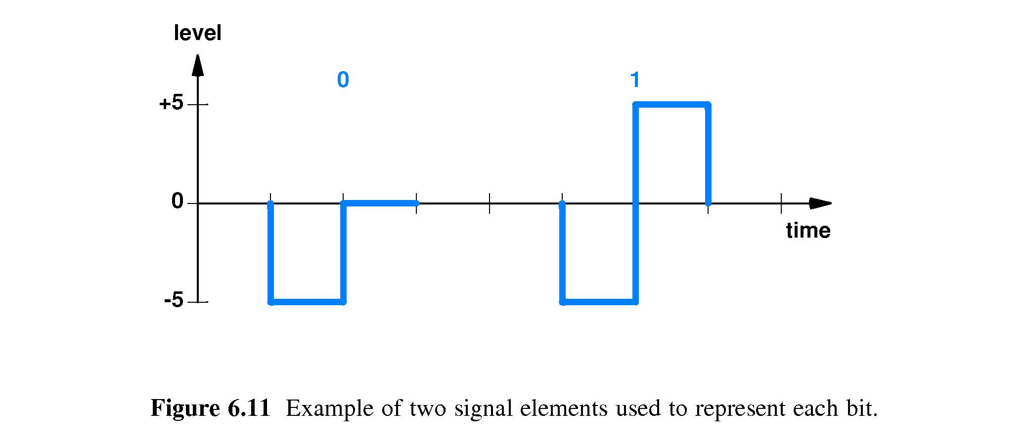
-
(over) simplified example: send -5 volts then 0 volts to represent a
zero-bit, -5 volts then +5 volts to represent a one-bit, and allow no
other patterns of voltages to be used.
- 6.16 Manchester Encoding Used in Computer Networks
-
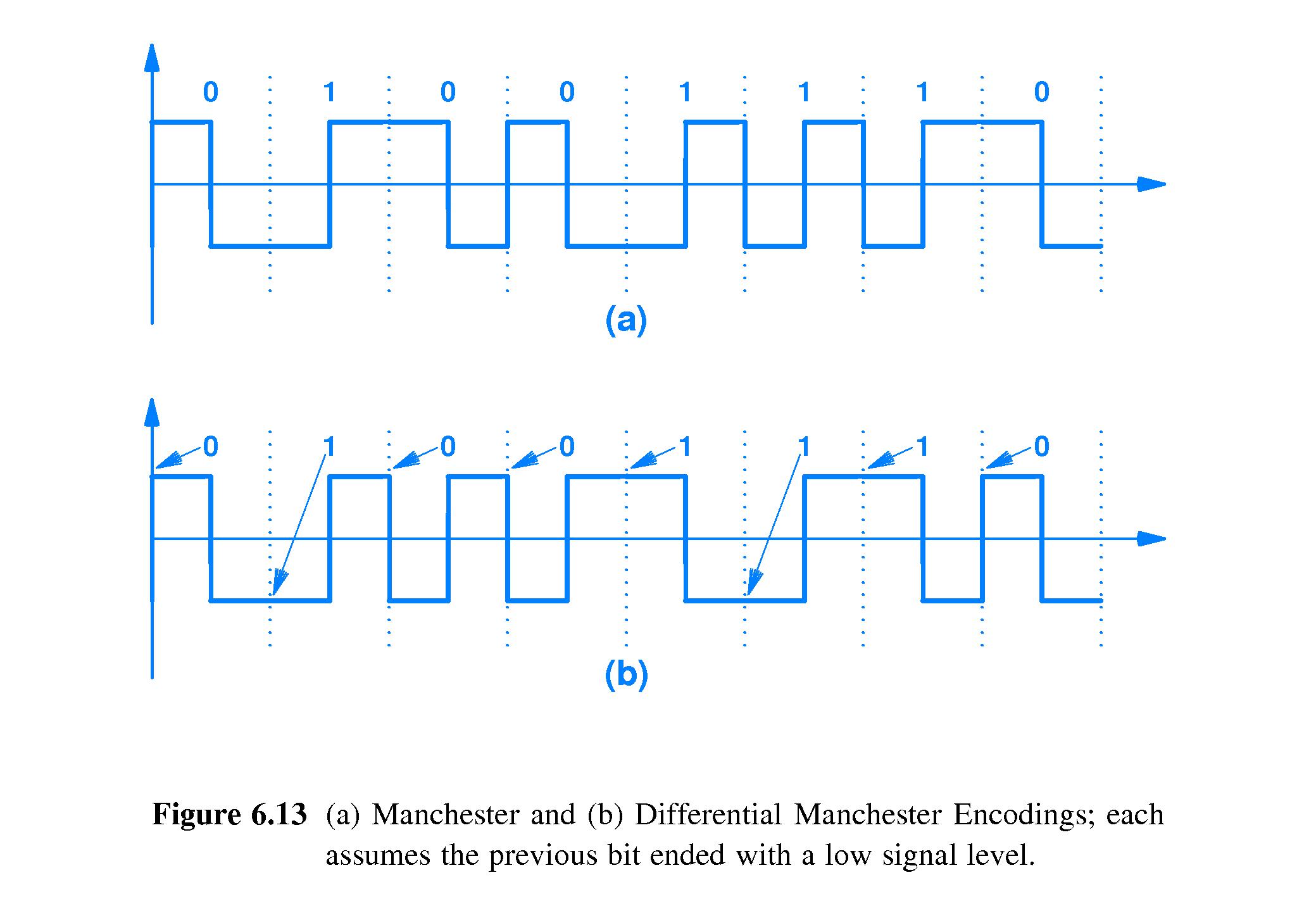
In the Manchester line coding used with Ethernet, it is transitions
from one voltage to another that symbolize bit values. It's not the
voltage levels themselves.
- A transition from 0 to a positive voltage in the middle of the time
slot allocated to a bit represents a 1.
- A transition from positive to 0 voltage in the middle of a "bit time"
represents a 0.
- Suppose two 0's or 1's in a row are needed. In that case the voltage
'flips' at the edge of the next bit time, and then flips again at the
middle of that bit time.
- There is also a Differential Manchester Encoding, In that scheme, the
edges of the bit times determine the bit values. If there is a flip
at the beginning of a bit time, that bit is a zero. If there is no
flip at the beginning of a bit time, that bit is a one. Also,
there's a flip in the middle of every bit time. (If not, a long
sequence of 1's might be dangerous.)
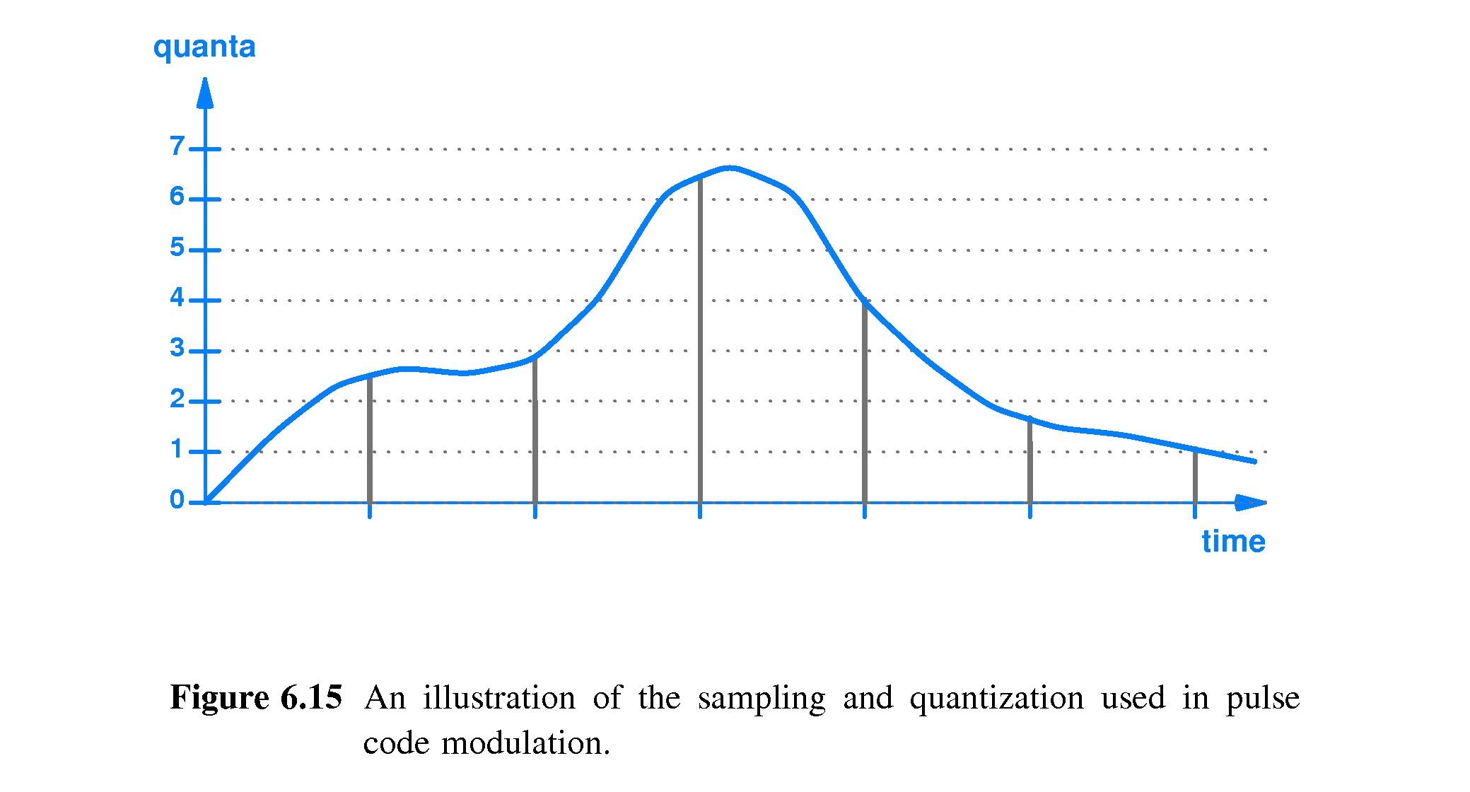
- 6.17 Converting an Analog Signal to Digital
-
Pulse Code Modulation is one way to represent an analog signal in
digital form.
- Suppose the analog signal ranges between 0 and 15 volts.
- We can
divide that range into 8 sub-intervals: interval 0: 0-1,
interval 1: 2-3, interval 2: 4-5, interval 3: 6-7, interval 4: 8-9,
interval 5: 10-11, interval 6: 12-13, and interval 7: 14-15.
- We can
sample the analog signal at times 0, T, 2T, 3T, 4T, 5T,
6T, and so on, for some suitable sampling interval T.
- If a sample is inside the first interval 0-1, we can encode
that as a 0, maybe by using a three bit representation "000".
- Likewise if the sample is in the range 2-3, we might encode
that as "001"
- Similarly we could use the other three-bit representations of
the numbers between 2 and 7 for intervals 2-7.
- We could
transmit the corresponding sequence of three-bit
codes.
It would be the translation of the analog signal to a digital
signal.
-
Delta Modulation is similar to Pulse Code Modulation, except that the
numbers transmitted represent the
difference in value between
successive samples.
- Delta modulation may require fewer bits per sample, but
- If something goes wrong with one of the transmitted values then
all the subsequent values transmitted will be misinterpreted.
- 6.18 The Nyquist Theorem and Sampling Rate
- Nyquist's theorem: if f cycles per second is the
highest frequency that must be preserved in the analog data (i.e. if
it must be preserved after the digital data is converted back to
analog) then
sample the analog signal at least 2f
times per second.
- 6.19 Nyquist Theorem and Telephone System Transmission
-
Voice quality is acceptable if frequencies between 0 and 4000 Hz
are preserved.
- Therefore the PCM standard for plain old telephone service (POTS)
uses 8000 samples per second (See the Nyquist Theorem).
- Each sample is mapped to one of 256 levels, and
is represented with an 8-bit pattern.
-
Thus digitized voice uses 8000 X 8 = 64,000 bits per second.
- 6.20 Nonlinear Encoding
-
Telephone companies actually use a variant of the kind of
PCM described in section 6.17.
- The algorithms use 8-bit samples and a sampling rate of
8000 per second.
- The μ-law algorithm is utilized in North America and Japan,
produces more dynamic range (louder sounds) than standard PCM,
but it also allows weak signals to become more distorted.
- With the a-law algorithm of Europe, dynamic range is reduced but
weak signals are better preserved.
- 6.21 Encoding and Data Compression
- To compress digital data is to
change its encoding in such a
way as to reduce the total number of bits required to represent the
data.
- Compressed data requires
less time to transmit, as well as less space to store.
-
Some compression is lossy, meaning that some of the original
information content cannot be recovered from the compressed version.
This may be acceptable for such things
as images, video and audio.
-
Lossless compression preserves all information, which
generally means that it is possible for the receiver to invert the
compression -- e.g. convert a compressed document back to its
original form.
- Most lossless compression involves substituting oft-repeated (long)
strings with a (short) code. A dictionary tabulates the codes. The
dictionary is transmitted along with the compressed document.