Notes On Chapter Twenty-Two
-- Datagram Forwarding
22.0 Study Guide
Know that the IP packet is called a datagram.
Know the basics of the structure of an IP datagram (both IPv4
and IPv6).
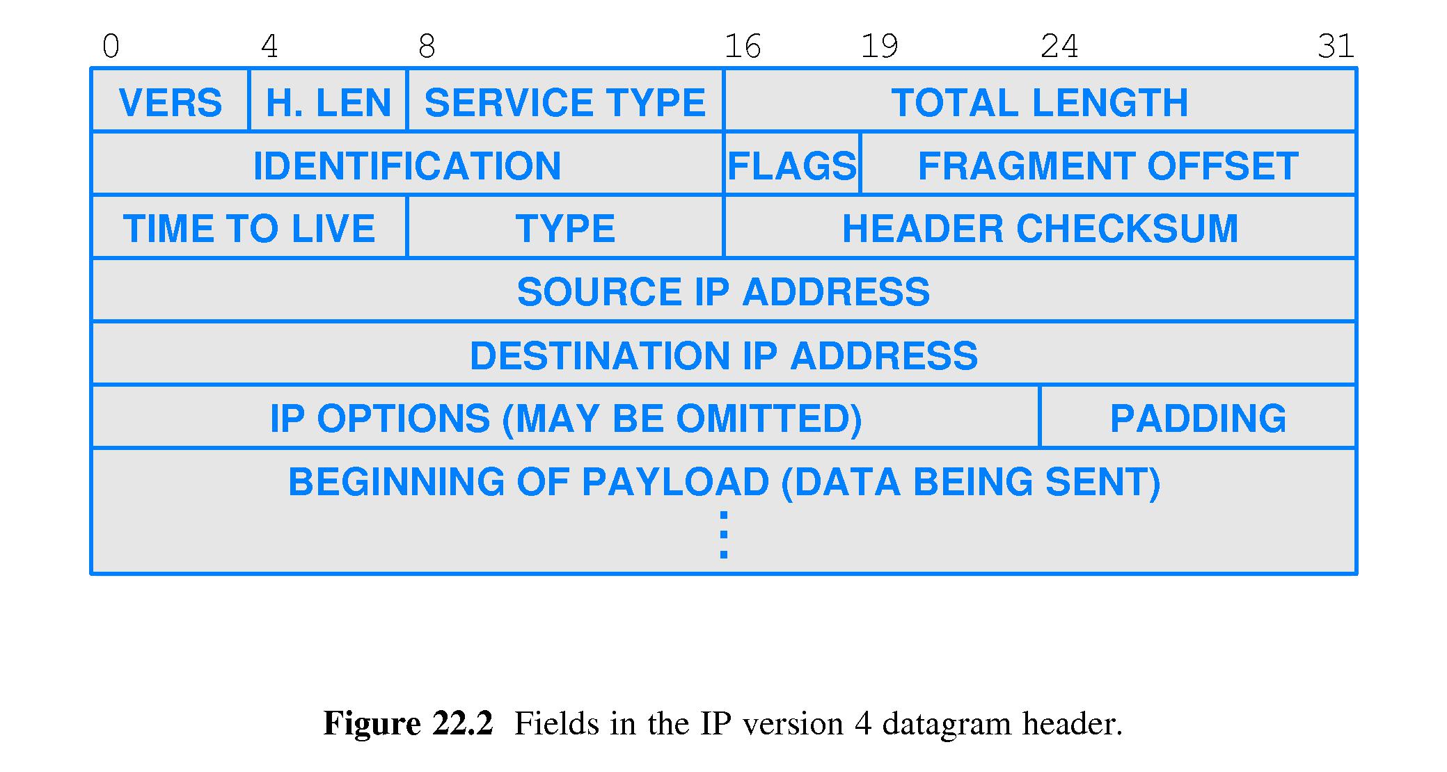
Know the basics of the structure of IP datagram
header(s) (both IPv4 and IPv6).
Understand the basics of the method used by IP routers to
forward IP datagrams - how destination addresses are matched
to entries in forwarding tables, using destination network addresses
and masks.
Understand that IP routers do not change the destination addresses in
IP datagrams.
Understand the limitations of the best-effort delivery service
furnished by the IP protocol.
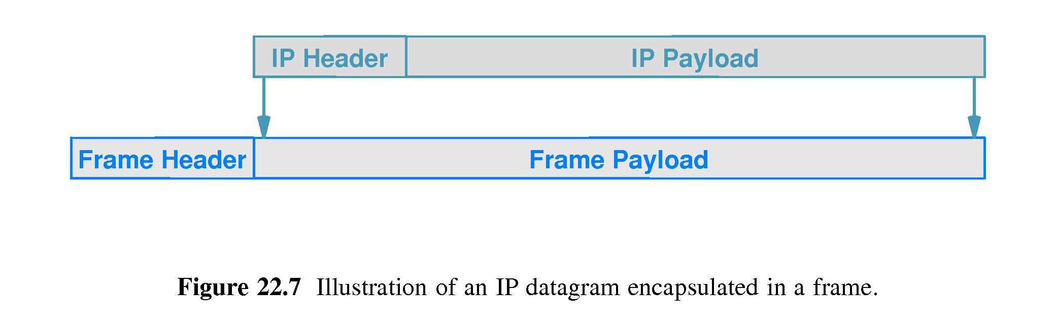
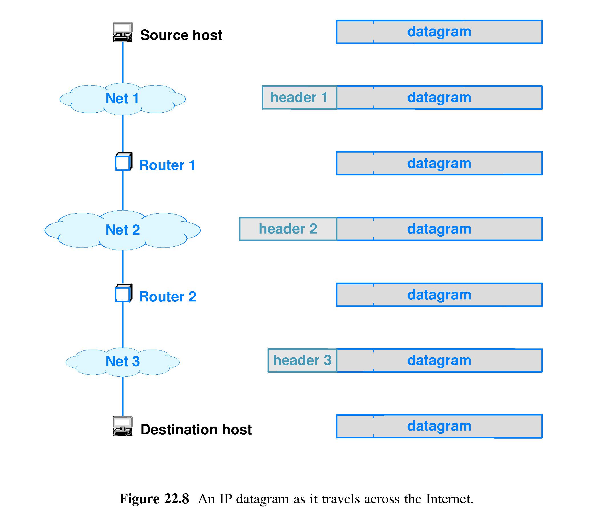
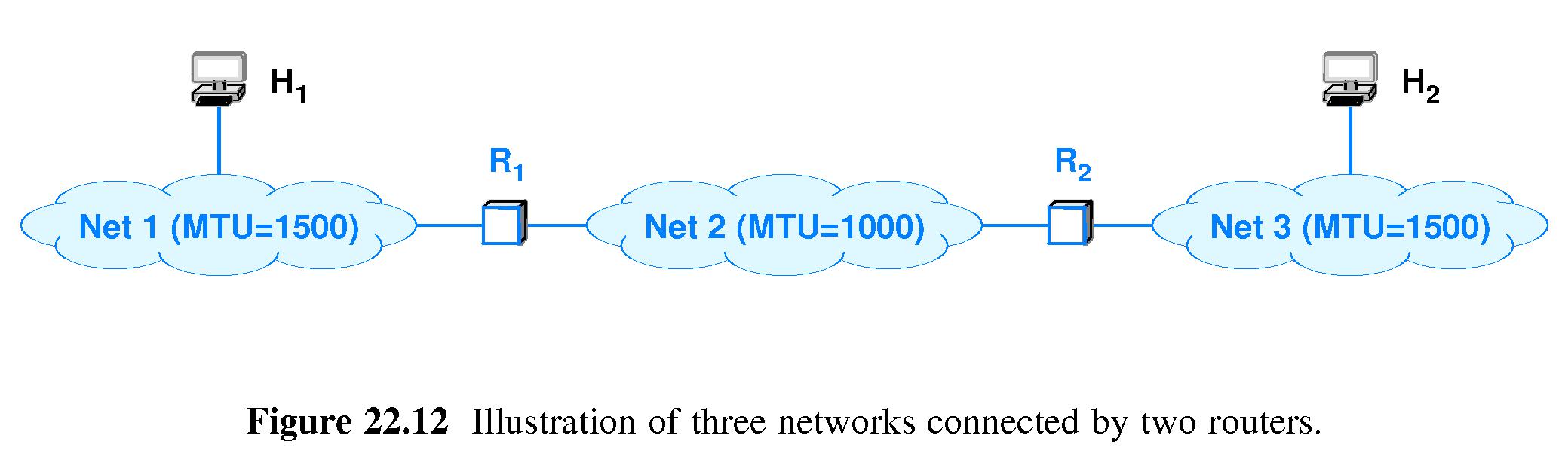
Understand how IP datagrams are encapsulated in physical network frames
for transmission across physical networks, and how things work when
IP datagrams are forwarded through a series of physical networks
connected by IP routers.
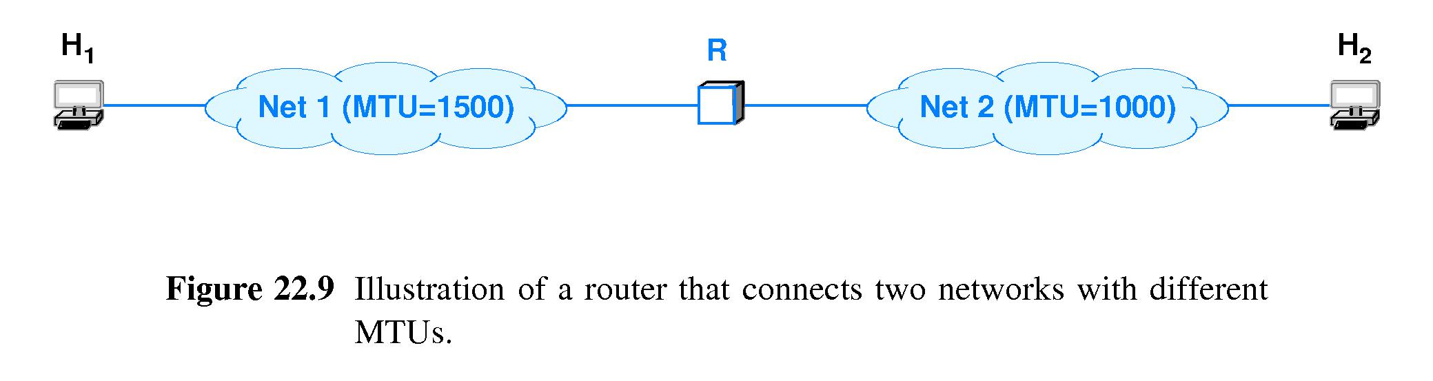
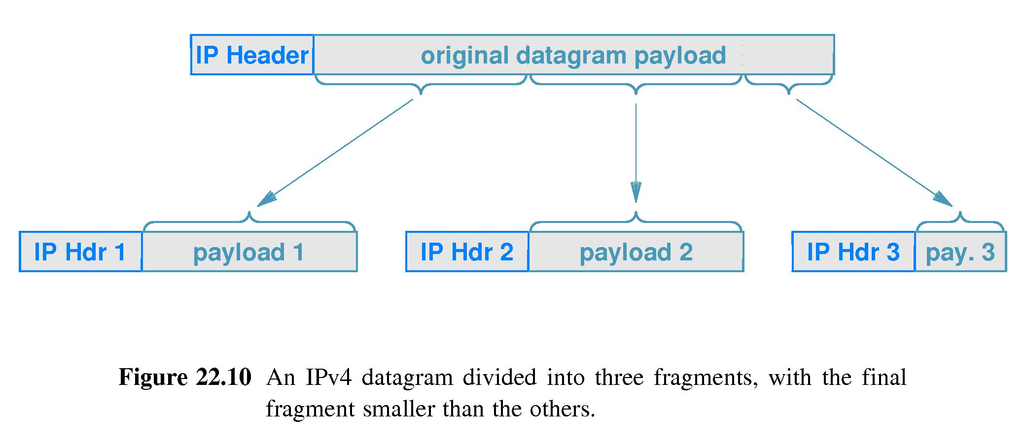
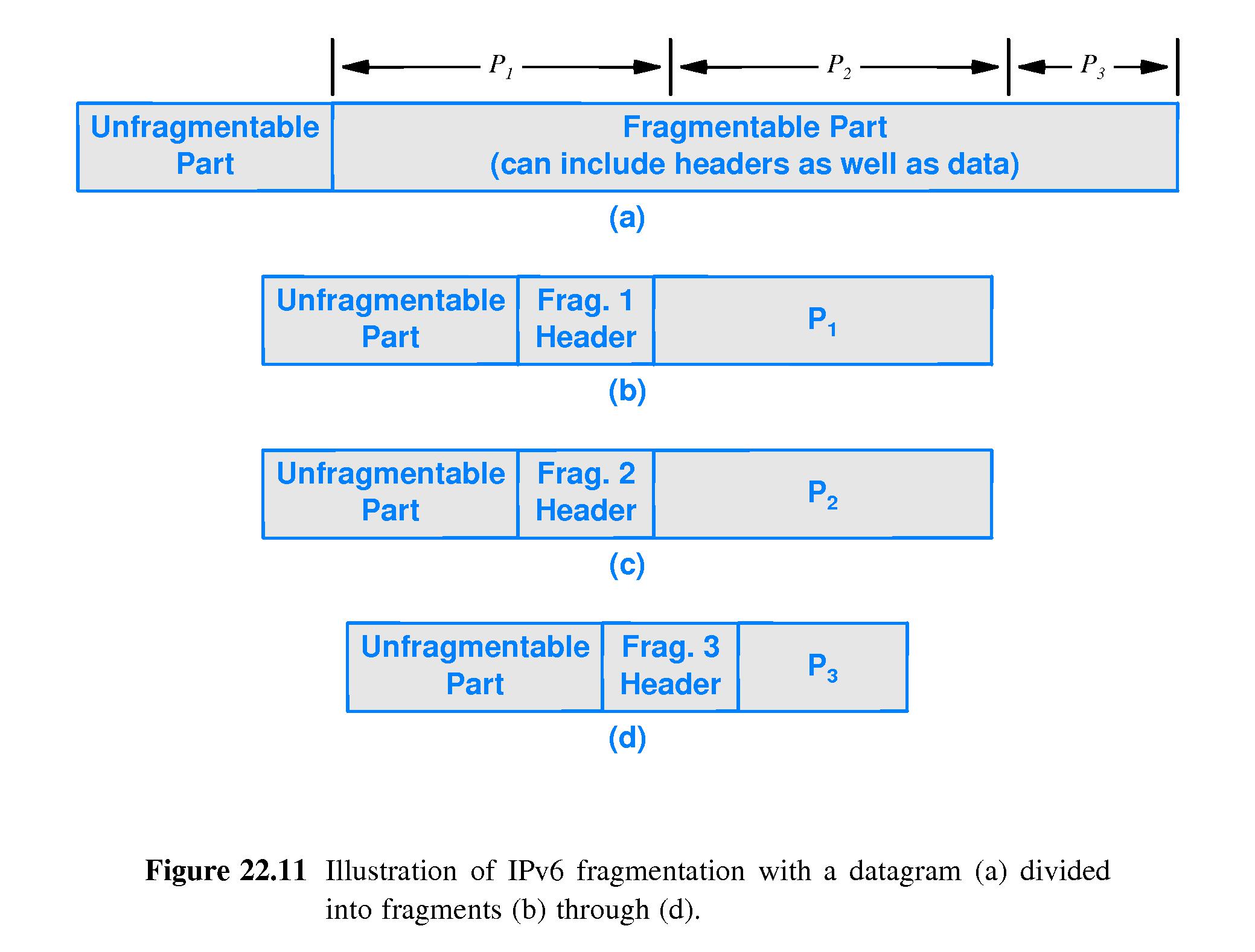
Understand what fragmentation is and why it may be necessary.
Understand what a network MTU is, and what a path MTU is.
Know, under IPv4, whose responsibility it is
to fragment datagrams, and whose responsibility it is
to reassemble fragments.
Know, under IPv6, whose responsibility it is
to fragment datagrams, and whose responsibility it is
to reassemble fragments.
22.1 Introduction
Internet communication service
Packet format
Encapsulation
Forwarding
Fragmentation and Reassembly
22.2 Connectionless Service
Fundamentally Internet service is connectionless and packet-based.
However, the Internet supports reliable connection-based service,
which is implemented using underlying connectionless service.
22.3 Virtual Packets
Because of incompatibilities among network hardware features and
addressing modes, implementation of the Internet requires a
hardware-independent address format and packet format.
Consequently, the Internet address and packet formats are
hardware-independent.
22.4 The IP Datagram
Formally, an IP packet is called an IP datagram.
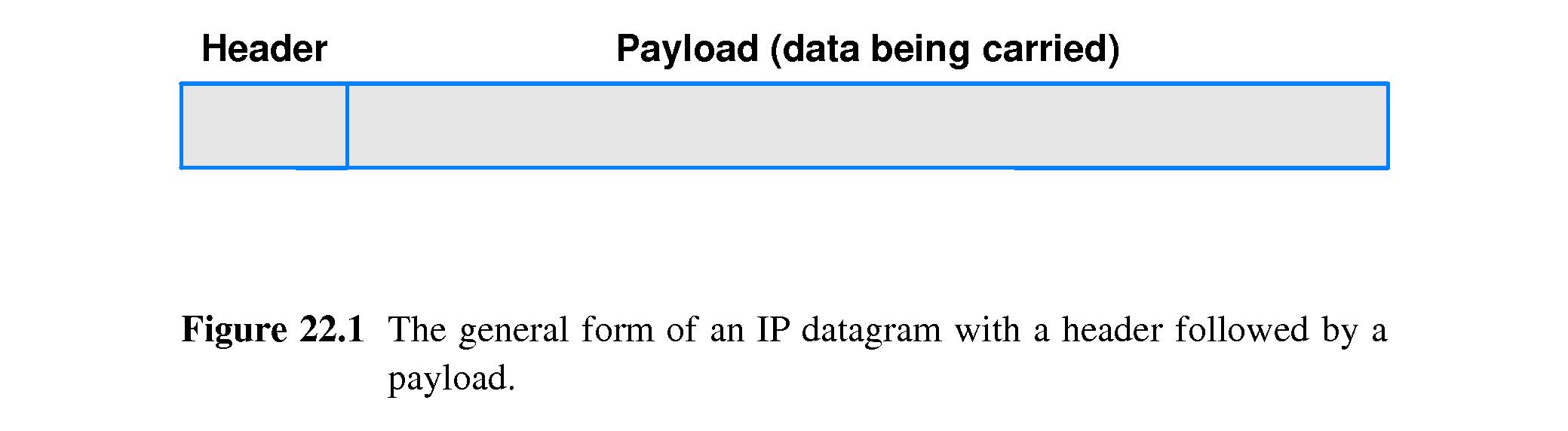
An IP datagram consists of a header followed by a data area.
The data area is often referred to as the payload.
The payload can be as small as one octet (an octet is 8 bits).
In IPv4, the combined size of the header and payload is
allowed to be as large as 64K octets (but no larger).
In IPv6, the payload itself is allowed to be up to 64K octets.
22.5 The IPv4 Datagram Header Format
There is a variable-sized header containing:
Source IP address
Destination IP address
Other stuff
There is a variable sized data area too -- important
flexibility for the wide range of uses of IP.
Although the IPv4 header can vary in size, each individual
field within the header is fixed in size.
22.6 The IPv6 Datagram Header Format
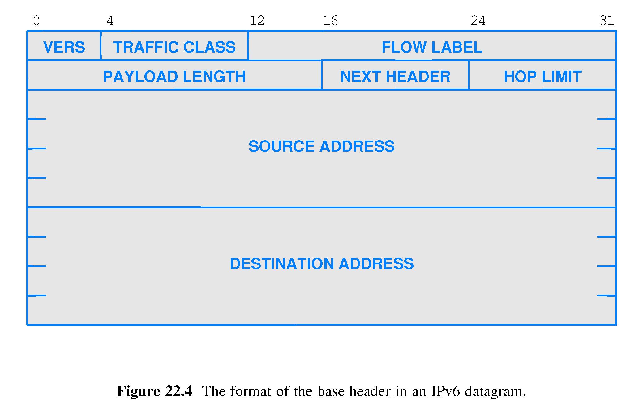
An IPv6 header consists of:
a base header, followed by
one or more extension headers, followed by
a payload.
22.7 IPv6 Base Header Format
Most of the content consists of the source and destination addresses,
both of which are 128-bit.
Other fields are as shown in figure 22.4
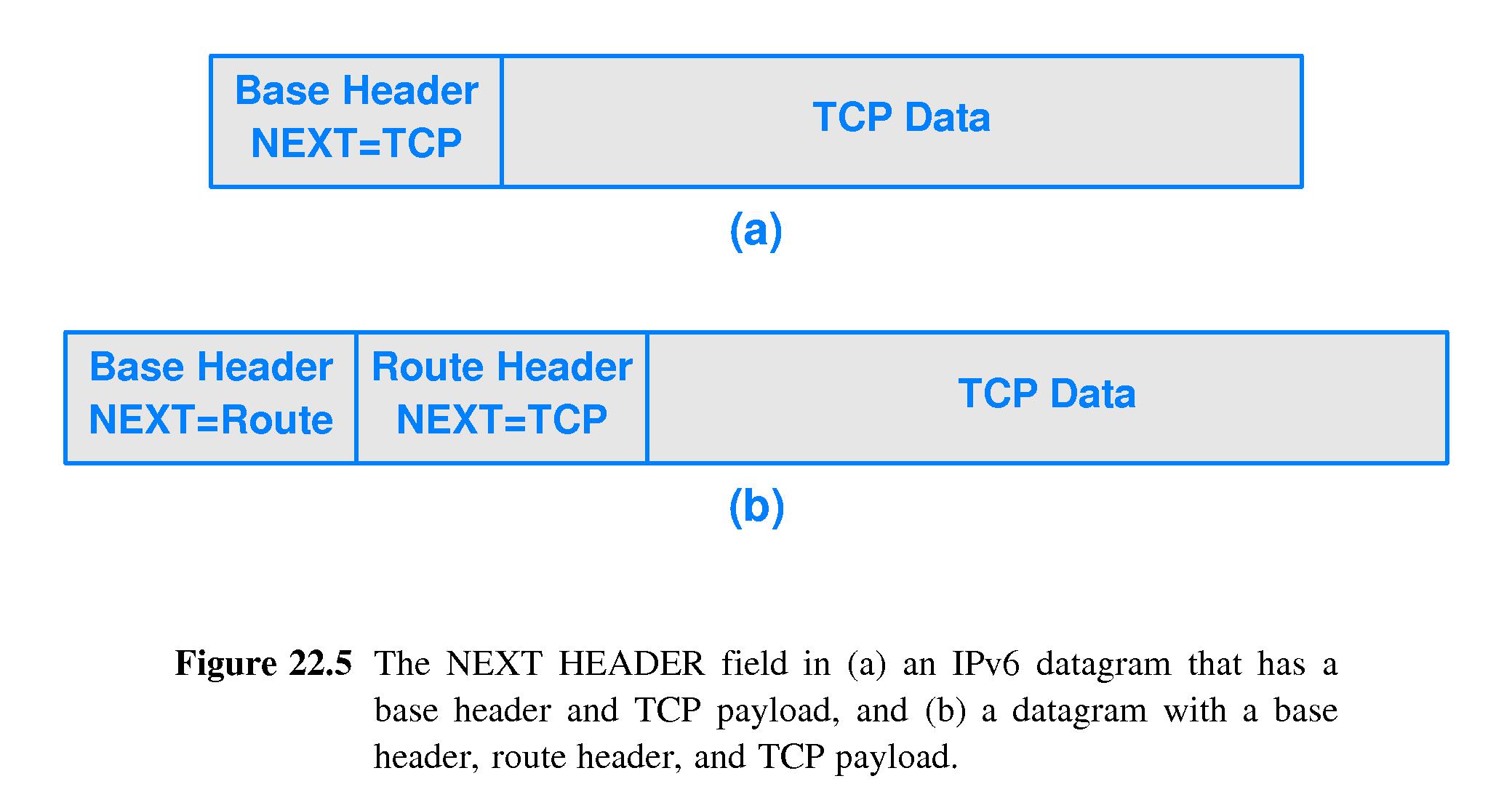
Notably there is a Next Header field to indicate the type of information
that comes next - an extension header or the payload.
Some extension headers are variable in length, and they have a length field.
22.8 Forwarding an IP Datagram
If an IP datagram is not addressed to a local destination, it is
forwarded from router to router until it reaches a router connected
to the destination network. That router forwards the packet to its
final destination.
The Internet uses next-hop forwarding.
Routers decide on the next hop based on the network prefix of the
destination address.
22.9 Network Prefix Extraction and Datagram Forwarding
Conceptually, each entry in a forwarding table contains three fields:
a Destination IP network address,
a Mask that encodes the prefix/suffix boundary of the
Destination network address, and
the IP address of a next hop to send packets addressed
to that Destination network.
To forward a packet with destination address D, the router examines
table entries until finding one such that:
Mask[i] & D == Destination[i]
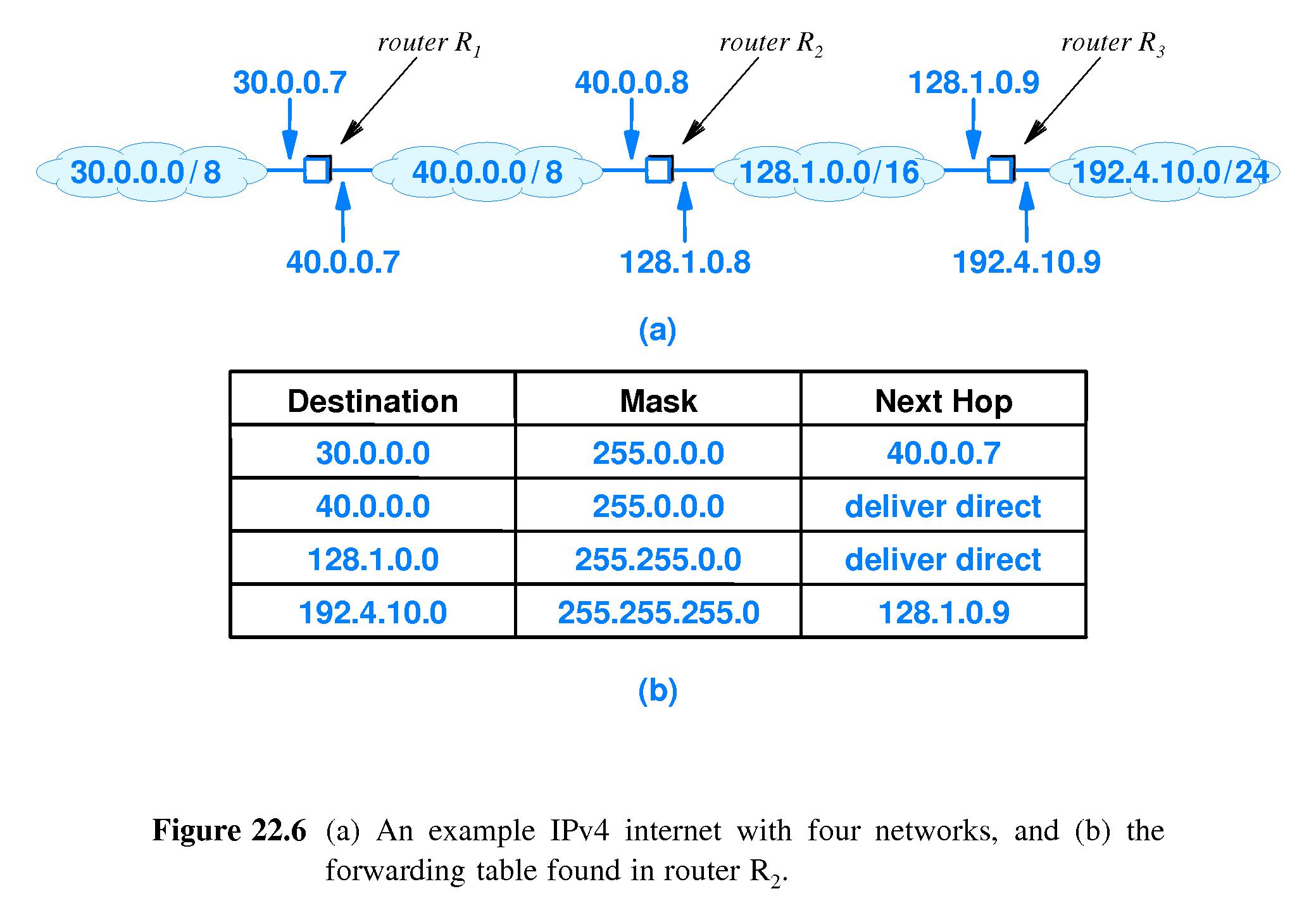
When such match is found the router decides to forward the packet to
NextHop[i].
As an exercise work out the forwarding of a packet with
destination address 192.4.10.3 arriving at center router,
R2, in figure 22.6 above.
In binary, D=192.4.10.3 is
11000000.00000100.00001010.00000011.
The first mask, Mask[0] is, 255.0.0.0,
which in binary is
11111111.00000000.00000000.00000000.
So Mask[0] & D is
11111111.00000000.00000000.00000000 &
11000000.00000100.00001010.00000011, which equals 11000000.00000000.00000000.00000000
The first network address in the table, Destination[0]
is 30.0.0.0, which is
00011110.00000000.00000000.00000000
in binary. That does not match Mask[0] & D.
The second network address in the table, Destination[1]
is 40.0.0.0, and Mask[1] is the same as Mask[0].
40.0.0.0 is
00101000.00000000.00000000.00000000
in binary. That does not match Mask[1] & D.
Looking at Mask[2], that's
11111111.11111111.00000000.00000000
in binary, and so Mask[2] & D is
11111111.11111111.00000000.00000000 &
11000000.00000100.00001010.00000011, which equals 11000000.00000100.00000000.00000000.
Destination[2] is 128.1.0.0, which is
10000000.00000001.00000000.00000000 in binary. Destination[2]
does not match Mask[2] & D.
Finally, Mask[3] is
11111111.11111111.11111111.00000000
in binary, and so Mask[3] & D is
11111111.11111111.11111111.00000000 &
11000000.00000100.00001010.00000011, which equals 11000000.00000100.00001010.00000000.
Destination[3] is 192.4.10.0, which is
11000000.00000100.00001010.00000000 in binary. Destination[3]
DOES match Mask[3] & D. Therefore we should route the datagram
with destination address D to the next hop address in row #3,
which is 128.1.0.9.
22.10 Longest Prefix Match
Internet routing algorithms provide support for default routes
and host-specific routes.
The matching method favors longer matching prefixes.
The result is that destinations are matched to the
most specific (most local) entry in the forwarding table.
Longest Prefix Matching makes host-specific routing work.
22.11 Destination Address and Next-Hop Address
The destination address in the IP datagram is always the IP address
of the final destination
In particular, the IP addresses of intermediate routers are NOT
entered into the IP datagram header (or payload).
22.12 Best-Effort Delivery
IP standards (including both IPv4 and IPv6) specify that IP
makes a "best-effort" to deliver each datagram.
However it does not guarantee that it will handle all problems.
The standard acknowledges the possibility of:
Datagram duplication
Delayed or out-of-order delivery
Corruption of data
Datagram loss
22.13 IP Encapsulation
When it's time to forward an IP datagram across a physical network,
the datagram is placed inside one of the frames used on the physical
network.
In other words, an IP datagram travels INSIDE a physical frame
(as the payload of the physical frame) when it is in transit.
The header of a physical frame typically has a type field. The
sender uses that type field to indicate that the payload of the
physical frame is an IP datagram. This helps the receiver know to
which protocol software the payload of the physical frame should be
forwarded.
The MAC destination address of the physical frame is the MAC address
of the next hop. For example, when one router sends an IP datagram
to a next-hop router, it puts the MAC address of the next-hop router
into the physical frame that encapsulates the IP datagram.
The last router in the chain needs to put the MAC address of the
destination host in the physical frame.
22.14 Transmission Across an Internet
Each time that a datagram is sent across a physical network, the
receiver on the other side, removes it from the encapsulating frame
and discards the frame.
If the IP datagram is forwarded along further, the router places
(only) the IP datagram into a new frame suitable to the next
network it must cross.
22.15 MTU and Datagram Fragmentation
Each physical network technology has a Maximum Transmission
Unit (MTU).
A frame can't be larger than the MTU, so some IP datagrams might be too
big to travel as the payload inside one frame.
Under IPv4, If a router needs to forward a datagram over a network but it is
too large for the network MTU, then the router can fragment the
datagram -- break it up into a series of smaller datagrams that are
each transmitted in a separate frame.
Under IPv6, the sending host is responsible for fragmentation.
Under IPv4, each fragment is a smaller IP datagram that contains a contiguous
section of the payload of the original datagram.
Under IPv4, the router encapsulates and transmits each fragment separately.
Under IPv4, the headers of the fragments are almost the same
as the header of the original datagram. However a bit is set to
indicate the datagram is a fragment, and there is a FRAGMENT OFFSET
field to specify where the fragment fits into the whole.
22.16 Fragmentation of An IPv6 Datagram
IPv6 puts fragment information in an extension header.
Some IPv6 headers must be used by intermediate routers.
They appear in every fragment.
Other headers are fragmentable.
Under IPv6 the sending host is required to do path MTU discovery
and to perform fragmentation, when necessary, that makes fragments small
enough for every network on the path from the source to the destination.
The sending host uses ICMP error messages to detect when it has sent
datagrams that are too large to reach the destination.
22.17 Reassembly Of An IP Datagram From Fragments
IPv4 fragments are identifiable by a FLAGs setting. IPv6 fragments
are identified by the fact that there is a (fragment) extension header.
The final fragment has a bit set in its header that helps the
computer that reassembles a datagram know when it has all the
fragments.
The final destination host is responsible for reassembly.
One advantage of that is that it allows busy routers to simplify
their work. They don't have to be aware of which datagrams are
fragments, and they don't have to do the reassembly work.
Another advantage is that if routes change and not all fragments are
forwarded to the same next-hop, it doesn't cause a problem with
reassembly.
22.18 Collecting the Fragments of a Datagram
The computer that reassembles a datagram that has been fragmented has
to determine:
Which fragments belong to which original IP datagrams?
Once we have all the fragments belonging to one particular
datagram, how do we figure out in what order they go back
together?
The computer figures out the answer to the first question by looking
at the combination of source IP address and unique datagram
identification number.
The answer to the second question is settled by examining the FRAGMENT
OFFSET fields in the fragments.
22.19 The Consequence of Fragment Loss
So as to avoid exhaustion of memory, a receiver sets a timer
when it first gets one of the fragments of an
IP datagram. If it does not receive all the fragments before the
timer expires, it discards all the fragments of that datagram.
There is no mechanism for the receiver to request that a fragment be
resent. Such a mechanism wouldn't make sense. Reassembly is 'all-or-none'.
22.20 Fragmenting a Fragment
The way that IPv6 fragmentation works, the fragments are
sized so they can be transmitted over the entire path between
the source and the destination.
The way IPv4 fragmentation works, fragments may arrive at
a router where they need to be further fragmented.
Fragments of fragments are just ordinary fragments.
It's simpler that way -- when reassembling, it's not necessary to
worry about first rebuilding fragments from sub-fragments before
rebuilding a datagram from its fragments.