(rev. Feb 19, 2017)
Notes On Chapter Seven
--
Transmission Media
- 7.1 Introduction
- media: wired, wireless, and optical
- concepts of electromagnetic propagation
- shielding
- capacity
- 7.2 Guided and Unguided Transmission
- wire and optical fiber are guided media - sometimes both referred to
as "wired"
- radio transmission is unguided, referred to as "wireless"
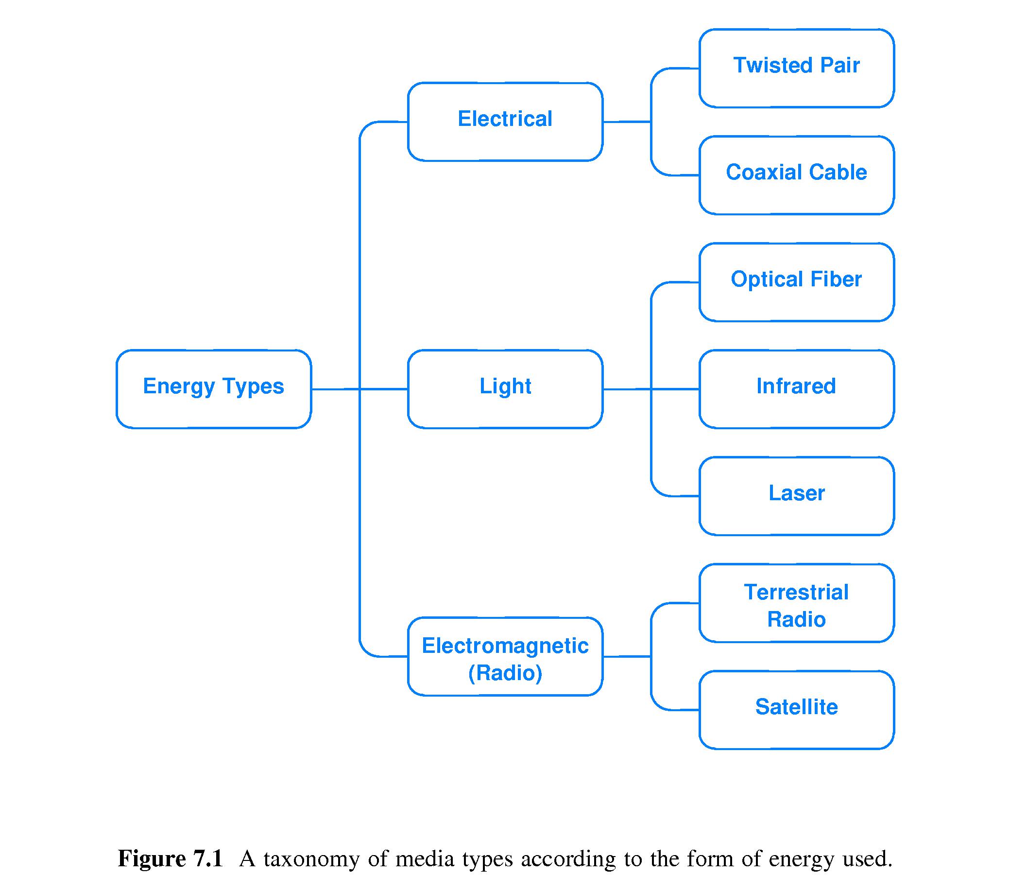
- 7.3 Taxonomy by Forms of Energy
- Energy Types
- Electrical
- twisted pair
- coaxial cable
- Light
- optical fiber
- infra red
- laser
- Radio (Electromagnetic)
- terrestrial radio
- satellite
- 7.4 Background Radiation and Electrical Noise
- Electrical flow requires a circuit.
-
Electromagnetic radiation caused by things like motors and
light fixtures can induce current flow - noise - in wires used for network
communication.
- Such induced electrical flow is noise that can corrupt the data
carried by the wires.
- Metal absorbs electromagnetic radiation, and so it can be used to
shield wires from the noise.
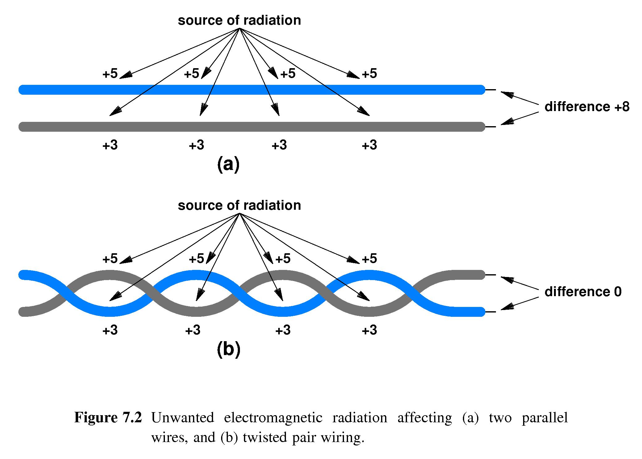
- 7.5 Twisted Pair Copper Wiring
- Two wires twisted together
- Each wire electrically insulated with plastic
- If wires are parallel, not twisted, then one is likely to shield the
other. If one wire in the circuit absorbs more radiation than the
other then the radiation is likely to cause a net change to the
electrical flow - noise.
-
If the wires are twisted, then each tends to be exposed equally to
radiation. Thus external radiation is less likely to have any net
effect on the electrical flow -
less chance of noise.
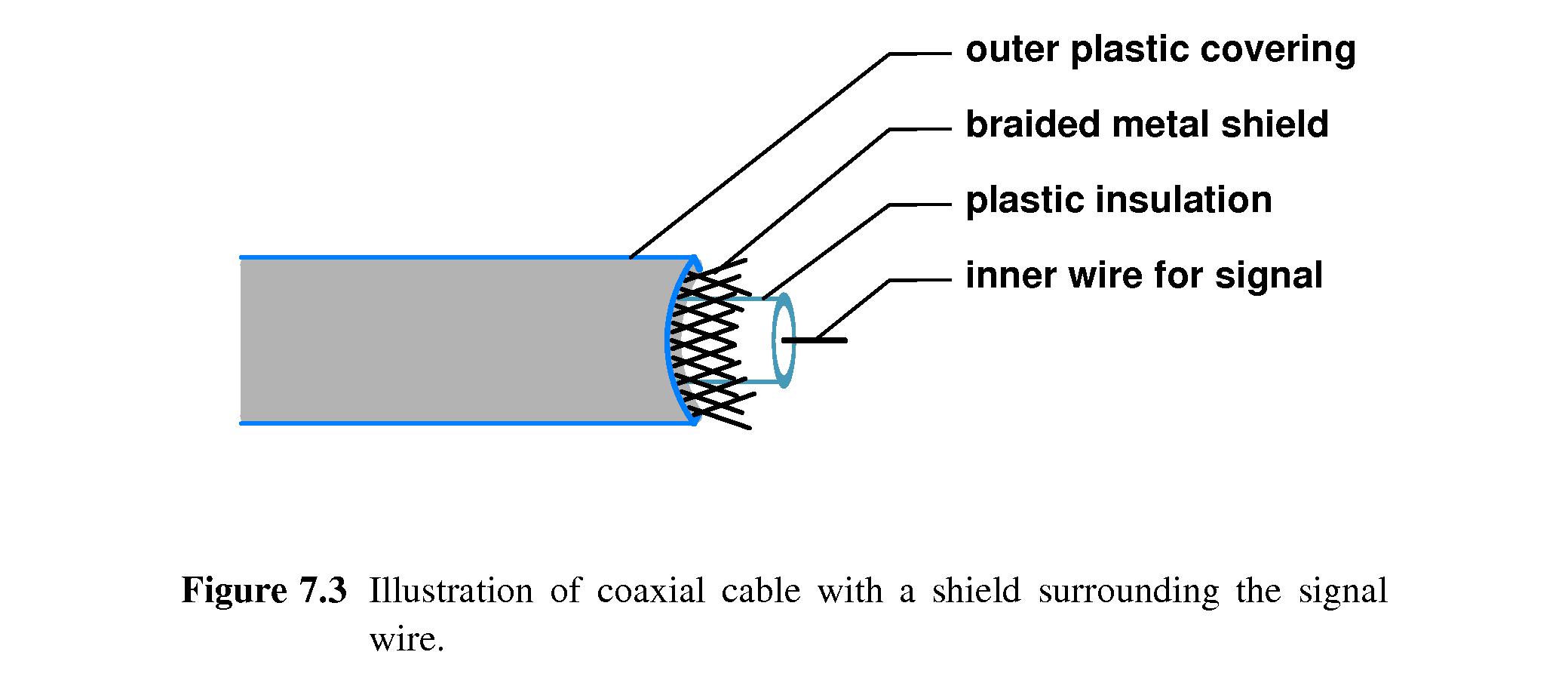
- 7.6 Shielding: Coaxial Cable and Shielded Twisted Pair
- Twisted pair wiring has problems when:
- the noise is especially strong or close, or
- when the data is transmitted at high frequency. (Much noise is
high-frequency.)
-
Coaxial cable is more effective at protecting network wiring in these
situations.
- A braided metal shield protects an inner signal wire from
interference, and other wires from the interference the signal wire
might cause.
- Shielded Twisted pair is a variation that is more flexible than
coaxial cable.
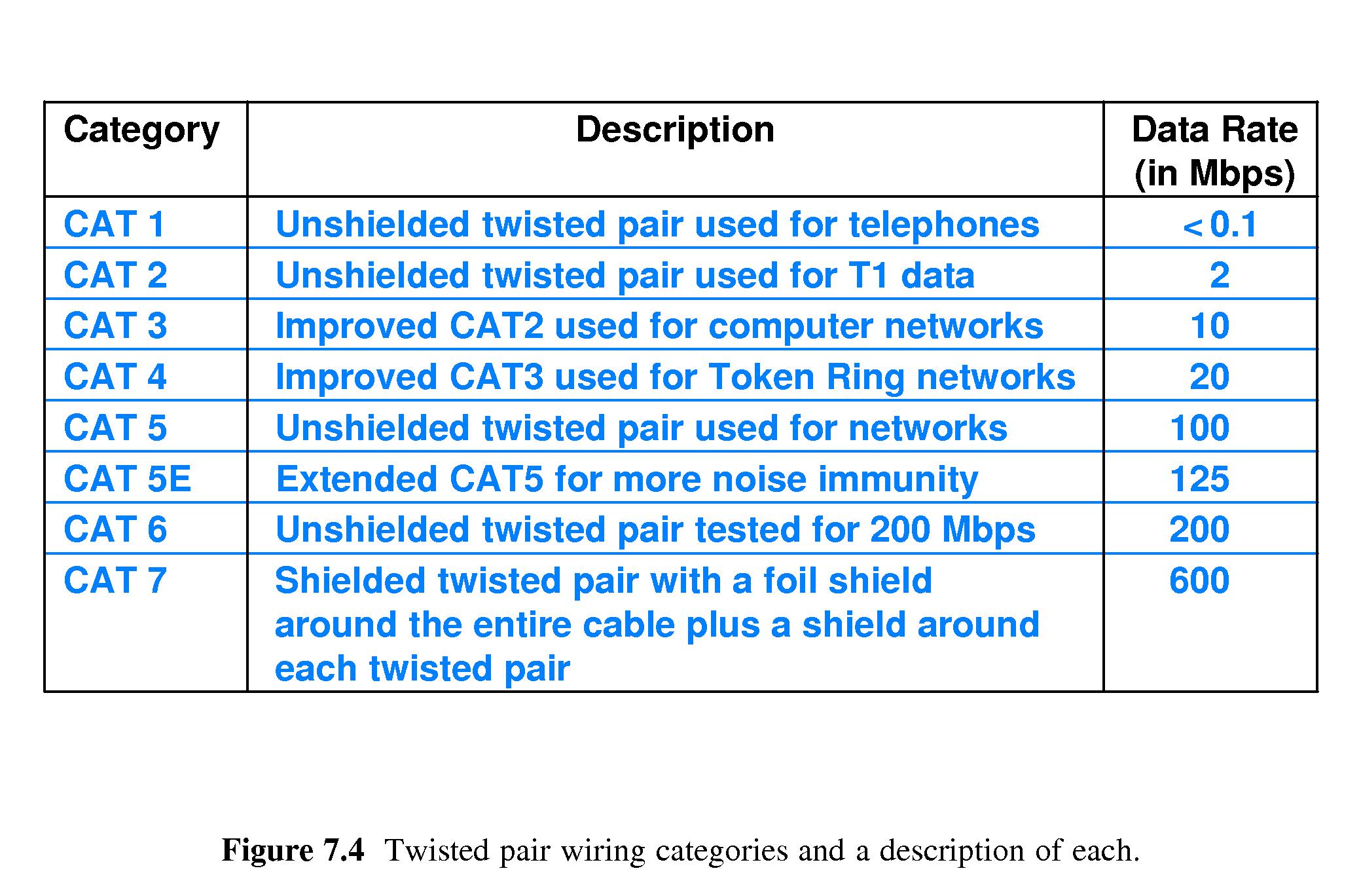
- 7.7 Categories of Twisted Pair Cable
- The American National Standards Institute (ANSI), the
Telecommunications Industry Association (TIA), and the Electronic
Industries Alliance (EIA) created specifications for
network wiring categories, for example
CAT 1 through CAT 7. (See page 118.)
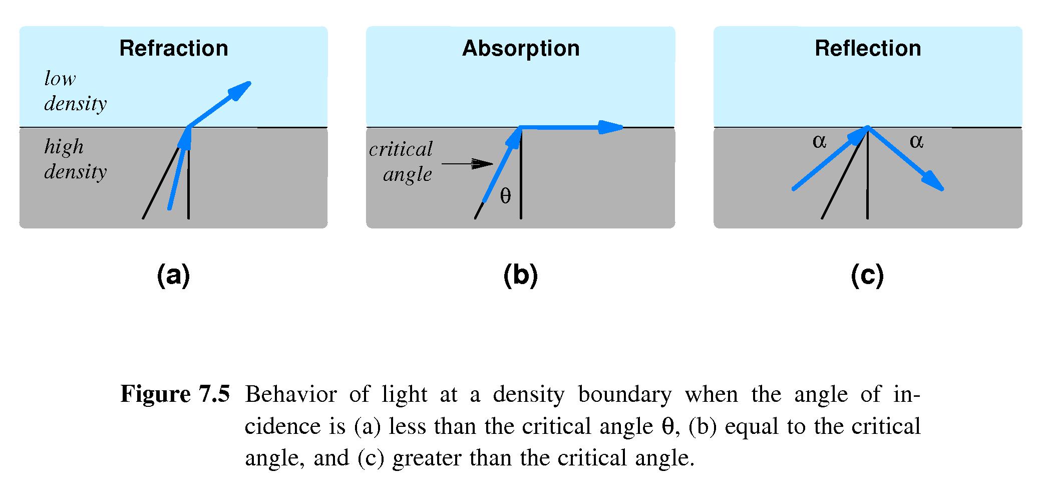
- 7.8 Media Using Light Energy and Optical Fibers
- Optical fibers are thin strands of glass or plastic surrounded by a
cladding that prevents light from leaking out.
- A laser or light-emitting diode (LED) at one end transmits.
- At the other end a device detects the incoming information.
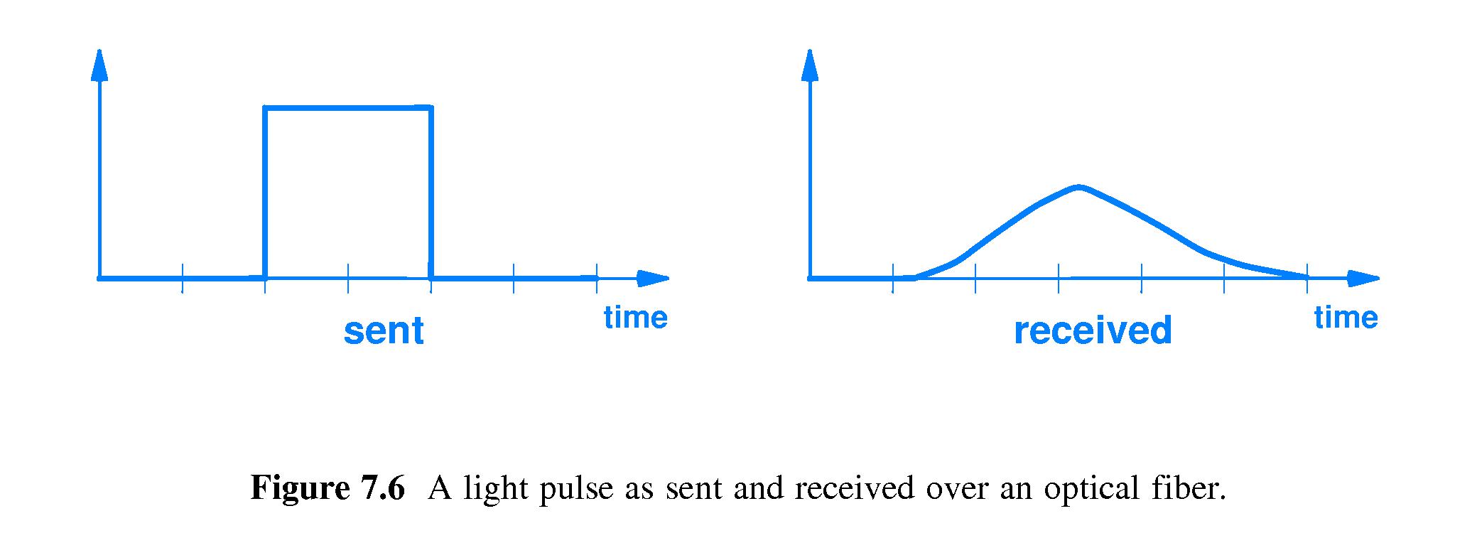
- Fiber is flexible - the light bounces around inside and keeps going
toward the destination, although there is significant dispersion
over longer distances.
- 7.9 Types of Fiber and Light Transmission
-
Three grades of optical fiber are:
- Multimode Step Index - high dispersion
- Multimode Graded Index - less dispersion
- Single Mode - least dispersion
-
Single Mode fiber is used for long distance, high bit-rate
applications.
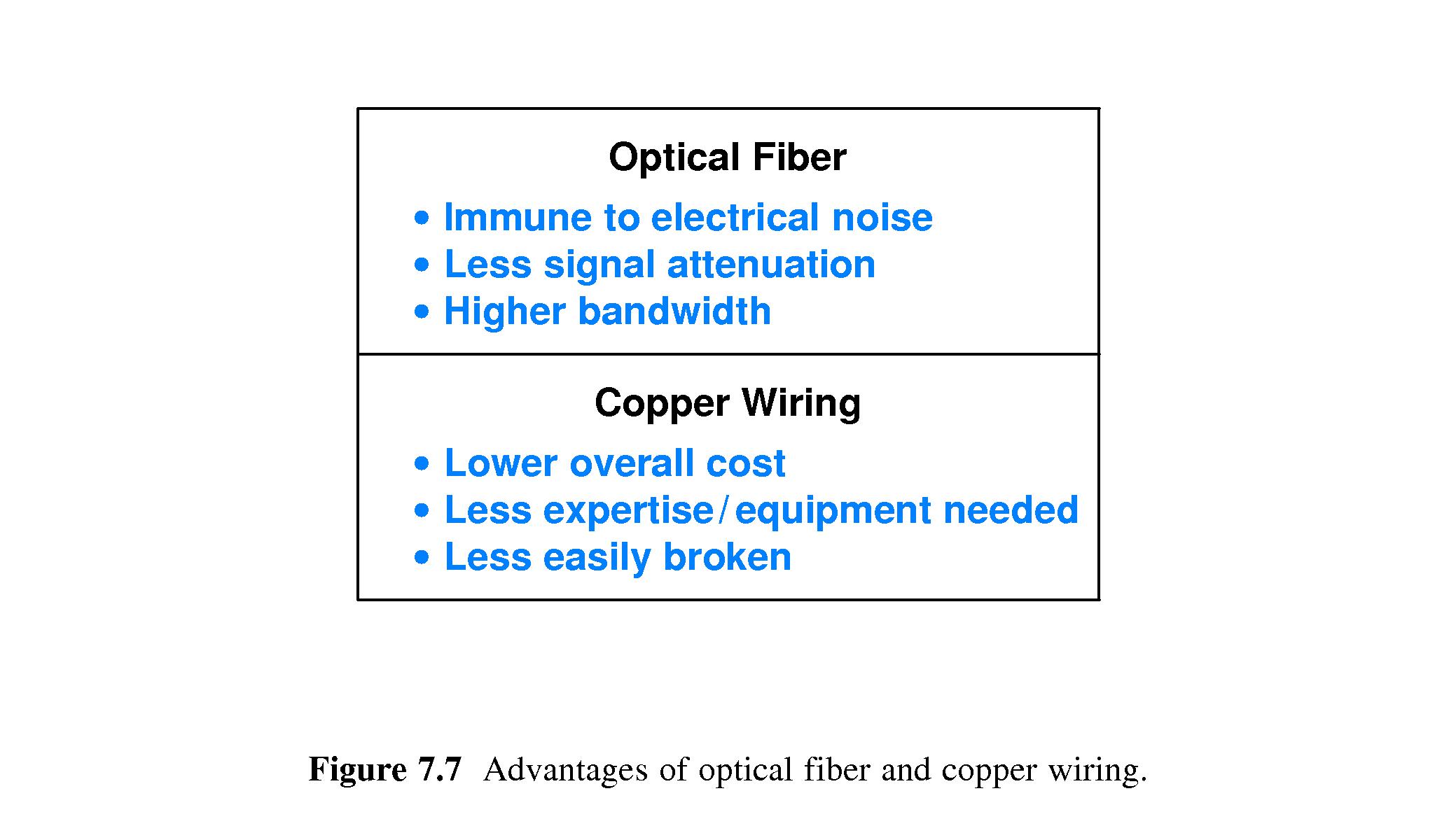
- 7.10 Optical Fiber Compared to Copper Wiring
-
Optical Fiber:
- is immune to electromagnetic interference
- has low attenuation
- has high bandwidth
-
Copper Wire:
- costs less
- requires less expertise and work to install
- is less likely to break
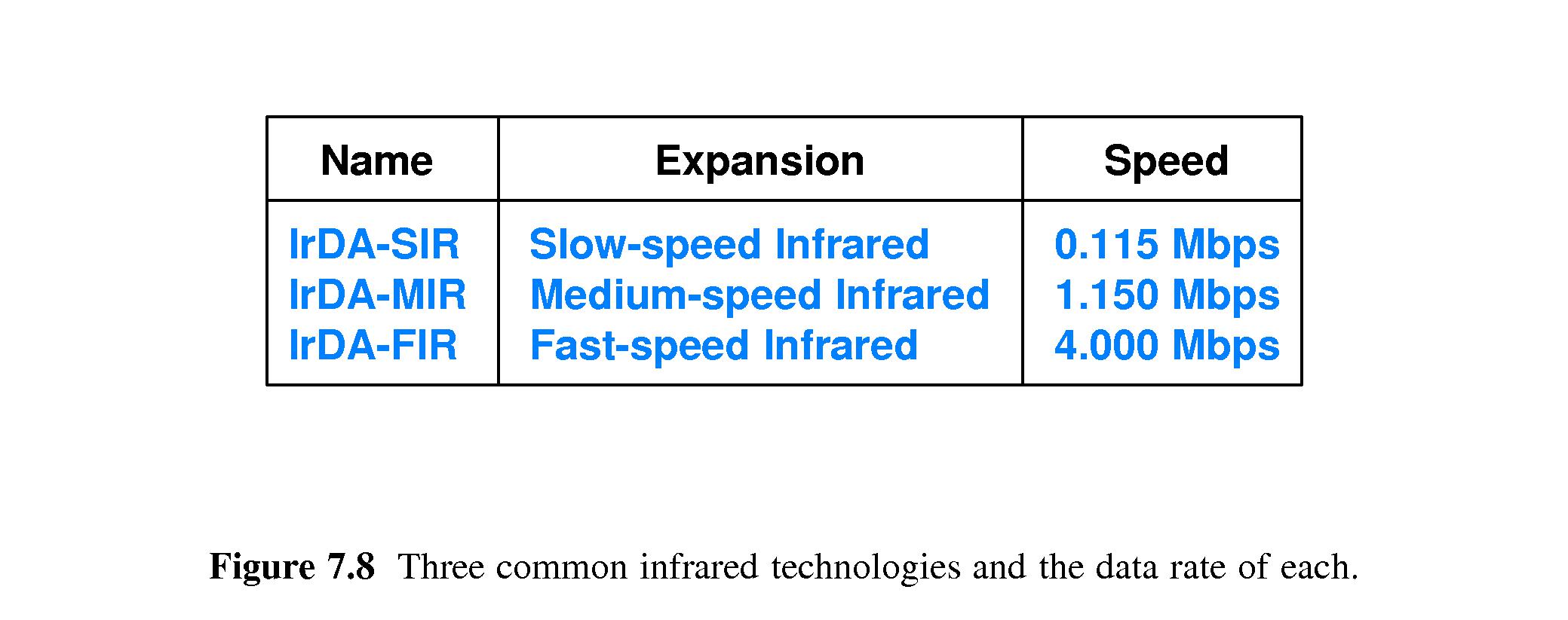
- 7.11 InfraRed Communication Technologies
- IR is just below the lowest colors of visible light that people can
see, and its characteristics are quite similar to visible light.
- IR disperses quickly, can reflect off a smooth hard surface, is easily
blocked by anything opaque, and is also blocked by moisture in the
air.
-
IR is good for indoor, low bandwidth applications,
where there are
clear lines of sight between communicating objects.
- Applications: TV remote controls, connections from computers to
printers and other peripherals.
- Bandwidth ranges from 100Kps to 4Mbps.
- 7.12 Point-To-Point Laser Communication
- Laser connections are similar to IR in some ways
- It requires clear line of sight and can be blocked by moisture in the
air.
- Unlike IR, the beam of light remains pencil-thin over a long
distance.
- It has relatively high bandwidth
- Transmitters and receivers must be precisely aligned.
-
It can be used outdoors as a substitute for stringing wires.
- Initial cost is high but upkeep is low.
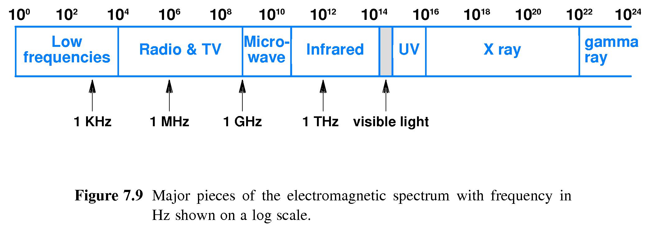
- 7.13 Electromagnetic (Radio) Communication
-
Radio Frequencies (RF) can travel long distances and
go through walls.
- RF ranges from about 3KHz to 300GHz
- Government agencies, like the FCC regulate the allocation of
electromagnetic frequencies for communication and the setting of
allowable power outputs at each range of frequencies.
- Frequencies:
- Low Frequencies: 100 to 104 Hz
- Radio and TV: 104 to 108 Hz
- Microwave: 108 to 1010 Hz
- Infra Red: 1010 to 1014 Hz
- Visible Light: 4 X 10¹⁴ to 7.9 X 10¹⁴ Hz
- Ultra Violet (UV): 1015 to 1016 Hz
- X-Rays: 1016 to 1022 Hz
- Gamma Rays: 1022 to 1024 Hz
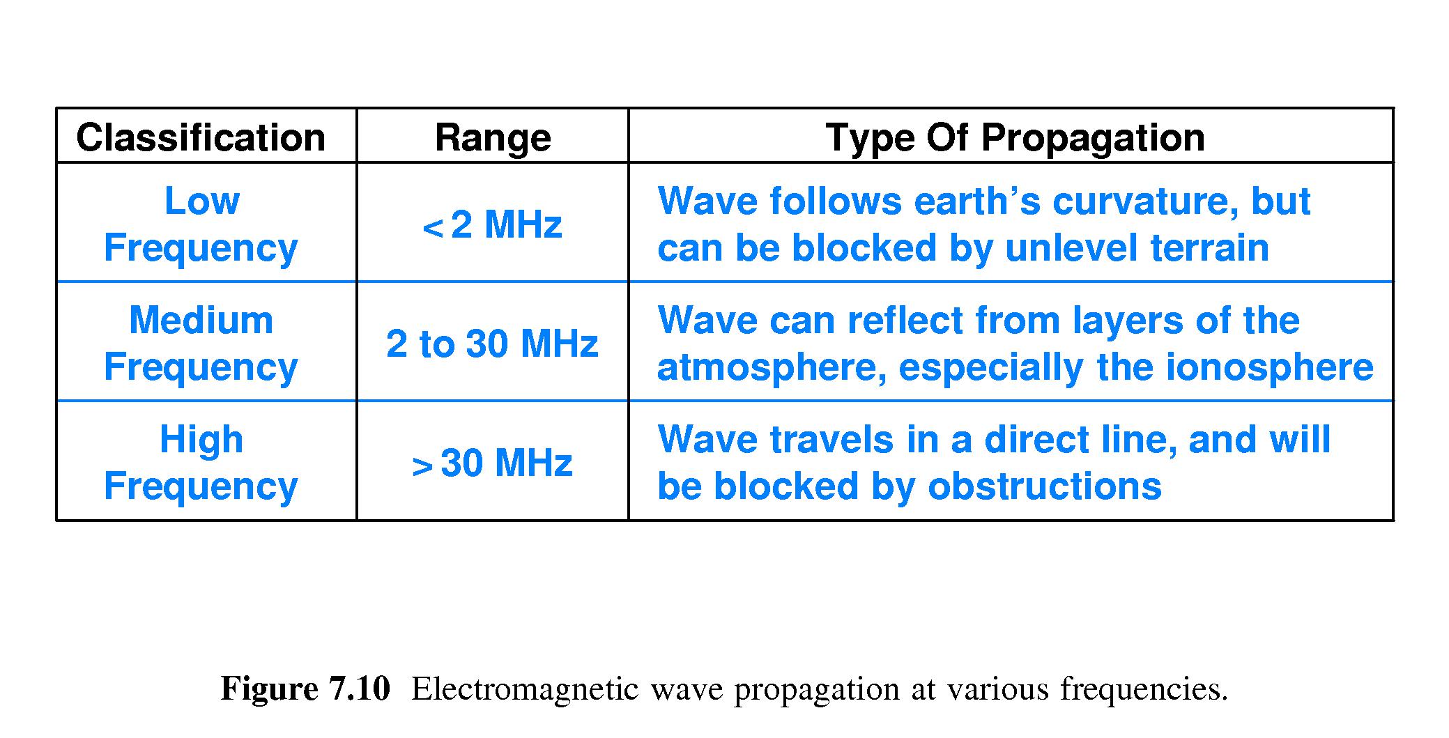
- 7.14 Signal Propagation
- An implication of Nyquist's theorem is that
the Baud rate on a
communication channel is limited to about twice the frequency.
- Low Frequency RF ranges up to 2 MHz and can follow the earth's
curvature.
- Medium Frequency RF ranges between 2 and 30 MHz and can reflect
off layers of the atmosphere (hence longer range).
- High Frequency RF can has frequencies above 30 MHz, but
is "line of sight."
- 7.15 Types of Satellites
-
Low Earth Orbit - low delay, they move in relation to observers on
ground.
-
Medium Earth Orbit - elliptical orbit - used for communication at the
poles.
-
Geostationary Earth Orbit - fixed position relative to earth, but
longer delay.
- 7.16 Geostationary Earth Orbit (GEO) Communication Satellites
- GEO satellites orbit at an altitude of 35,785 kilometers,
where
the orbital period is exactly one day. That's 22,236
miles - about 90% of the distance around the world.
- Thus a GEO satellite orbiting in the plane of the earth's equator
remains stationary directly over one location on the earth.
-
Antenna's don't have to be continually re-aimed at such a
GEO satellite.
- The
ground-to-GEO-satellite delay for a communication
signal is about 0.119 seconds -
about 1/8 of one second.
- For some applications, this delay is significant.
- Notice that a 1/8 ground-to-bird delay implies a
1/2 second delay for a round trip
between two distant points on the earth.
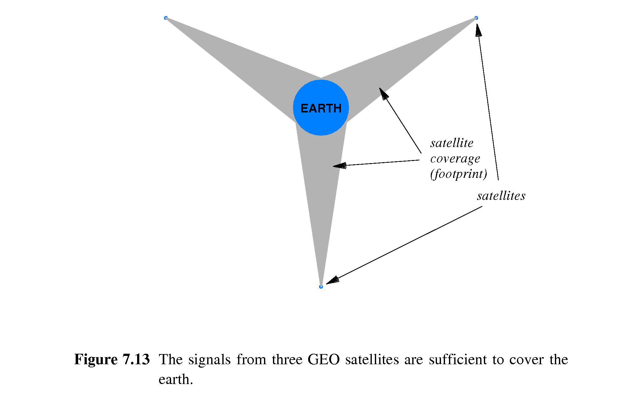
- 7.17 GEO Coverage of the Earth
-
If GEO satellites are too close together, their transmissions will
interfere with each other.
- At current power levels, there is room for 45-90 GEO satellites in
orbit above the equator.
-
Three such satellites at a separation of 120-degrees provide coverage
of the 'entire earth' -- in other words, from any point on the earth,
at least one of them can be observed in the sky. (There are probably
locations near the north and south poles where none are visible or
where the only ones visible touch the horizon.)
- 7.18 Low Earth Orbit (LEO) Satellites and Clusters
- Low Earth Orbit Satellites operate at altitudes of 500 to 2000
kilometers (300-1200 miles).
-
Delays are in the 1 to 5 millisecond range.
-
Tracking from the ground is difficult because the satellites move
very fast relative to the ground.
-
Typically LEO satellites work as clusters, for example:
- ground talks to satellite over Paris
- satellite over Paris relays to satellite X
- X relays to satellite Y, Y to Z.
- This continues until the information is relayed to a satellite
currently over the intended destination, say Tokyo.
- Finally the satellite over Tokyo transmits the information to a
receiver on the ground.
- 7.19 Tradeoffs Among Media Types
-
Consideration must be give to:
- Cost: of materials, installation, operation and maintenance
- Data Rate: Number of bits per second that can be sent
- Delay: time required for propagation and processing
- Effects on Signals: attenuation and distortion
- Environment: susceptibility to interference/noise
- Security: susceptibility to eavesdropping/sabotage
- 7.20 Measuring Transmission Media
- One can derive the following from Nyquist's theorem:
The Max Data Rate on a Communication channel is twice the (analog) bandwidth
times the base-two log of the number of possible signal levels.
- In symbols: Dmax = 2 B log2K
- 7.21 The Effect of Noise on Communication
- The Shannon-Hartley Law expresses how the presence of noise
puts limitations on maximum data rates:
- The maximum channel capacity is the product of the hardware bandwidth
and the the base-two log of one plus the signal-to-noise ratio.
-
In symbols: Dmax = B log2(1 + S/N)
- S and N are the power levels of the signal and the noise.
- For example, if B=1000 Hz, S=70 and N=10, then the Shannon-Hartley
Law predicts that no more than 3,000 bits per second can be
effectively sent on the channel.
- Sometimes a signal to noise ratio is converted to
decibels:
- dB = 10 log10(S/N)
- 7.22 The Significance of Channel Capacity
-
Nyquist's theorem encourages us to look for clever ways to increase
data transmission rates (media with higher bandwidth, better ways to
encode more signal levels).
-
The Shannon-Hartley Law reminds us that things such as
background radiation
present everywhere in the universe
will always be there holding us back
from achieving ideal data rates.