(rev. March 29, 2015)
Notes On Chapter Eighteen
-- WAN Technologies and Dynamic Routing
- 18.0 Study Guide
- Be able to explain what a packet switch is, what kinds of connections
it has, and what it can do
- Be able to describe how WANs are constructed from computers,
packet switches, digital circuits, routing tables and forwarding
algorithms.
- Be able to explain the store-and-forward paradigm utilized by
packet switches.
- Be able to explain the type of hierarchical addressing used in WANs,
and how the forwarding of packets relates to hierarchical addresses.
- Be able to explain next-hop forwarding
- Be able to explain source independent routing
- Be able to explain default routes
- Be able to explain the fundamental characteristics of
link-state routing (LSR) and distance-vector routing (DVR)
- 18.1 Introduction
- WAN structure
- Basic WAN components (packet switches)
- The concept of Routing
- Routing algorithms
- 18.2 Large Spans and Wide Area Networks
- True WAN technology is scalable - able to grow and deliver
reasonable performance, connecting many widely-separated sites, each
containing a large number of hosts.
- 18.3 Traditional WAN Architecture
- Most WANs today use Internet technology - routers connected
(usually) by leased circuits
- However, information in this chapter explains WANs in a
historical context.
- WANs predate LANs and the Internet
- Early WANs were designed to connect sites that each had just a few
large computers.
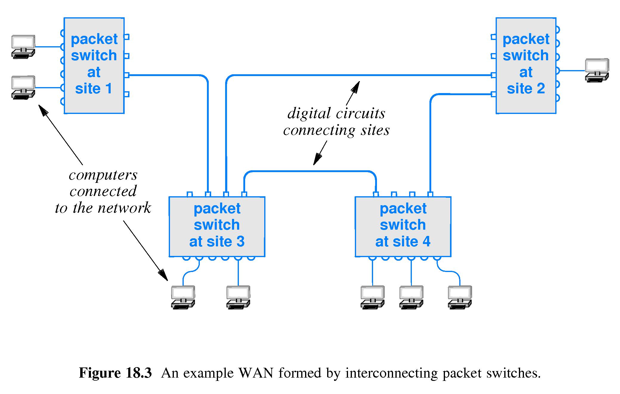
- Early WANs consisted of digital circuits between sites, computers at
the sites, and packet switches.
- Packet switches had interfaces of one kind for accepting inter-site
digital connections.
- Packet switches had other interfaces for accepting slower data
connections from computers at the local site.
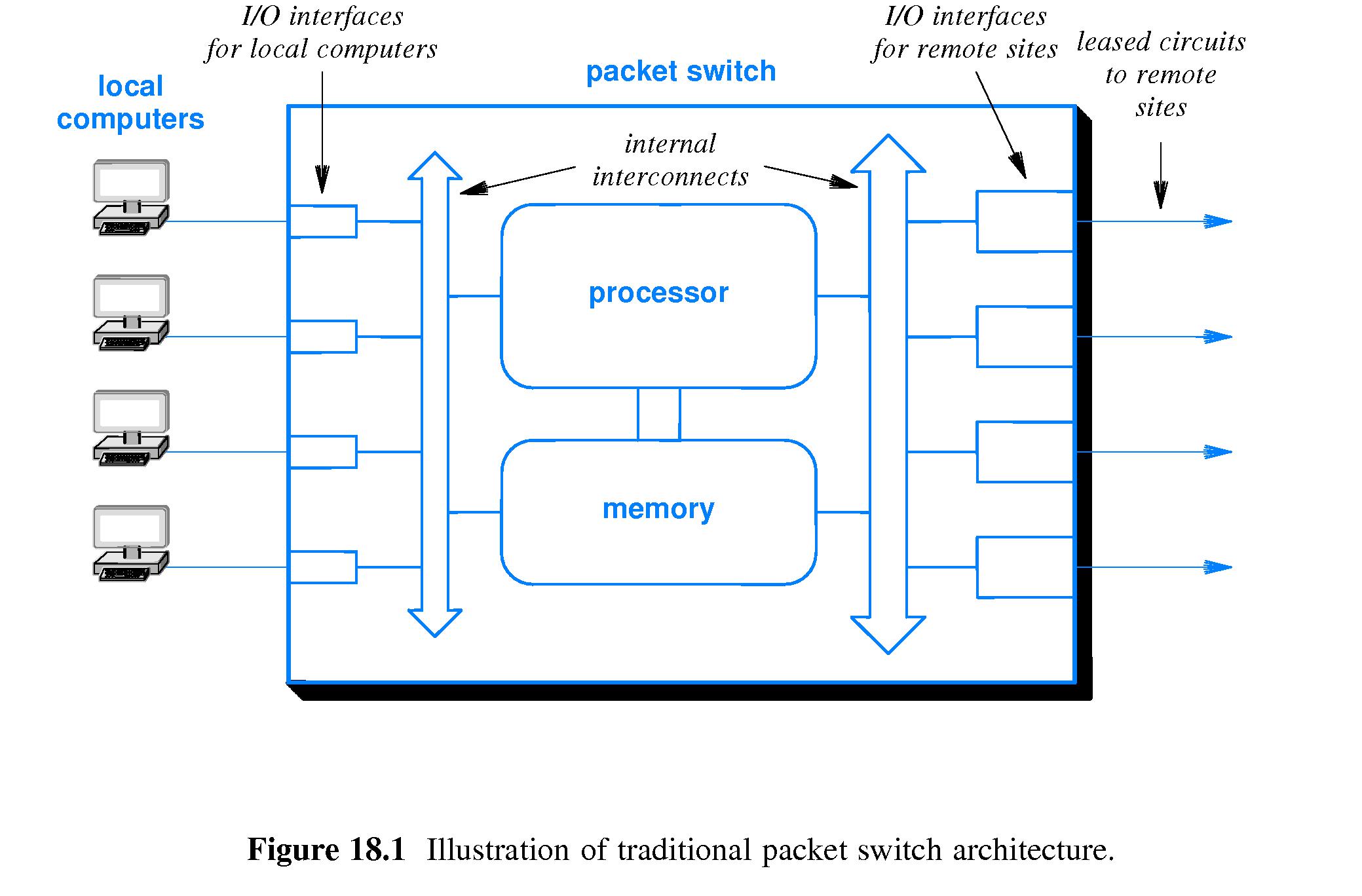
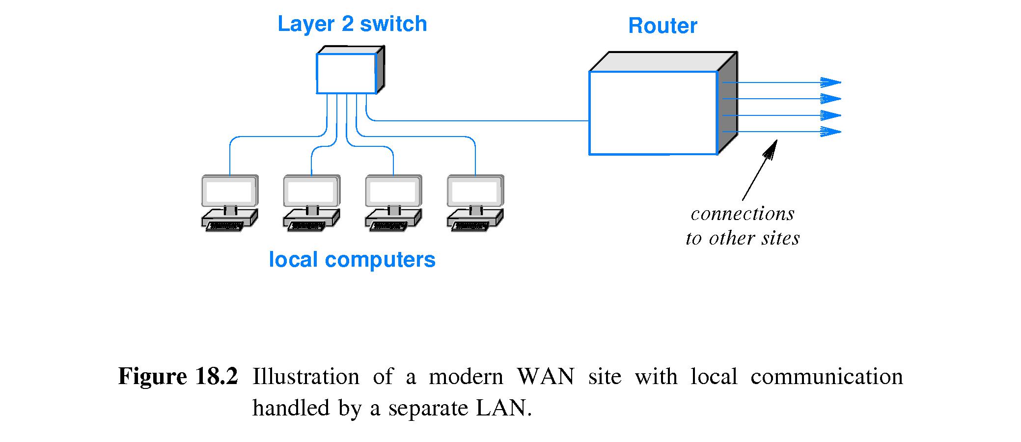
- Usually nowadays the functionality of a WAN packet switch is
achieved by combining one or more LAN switches with a router.
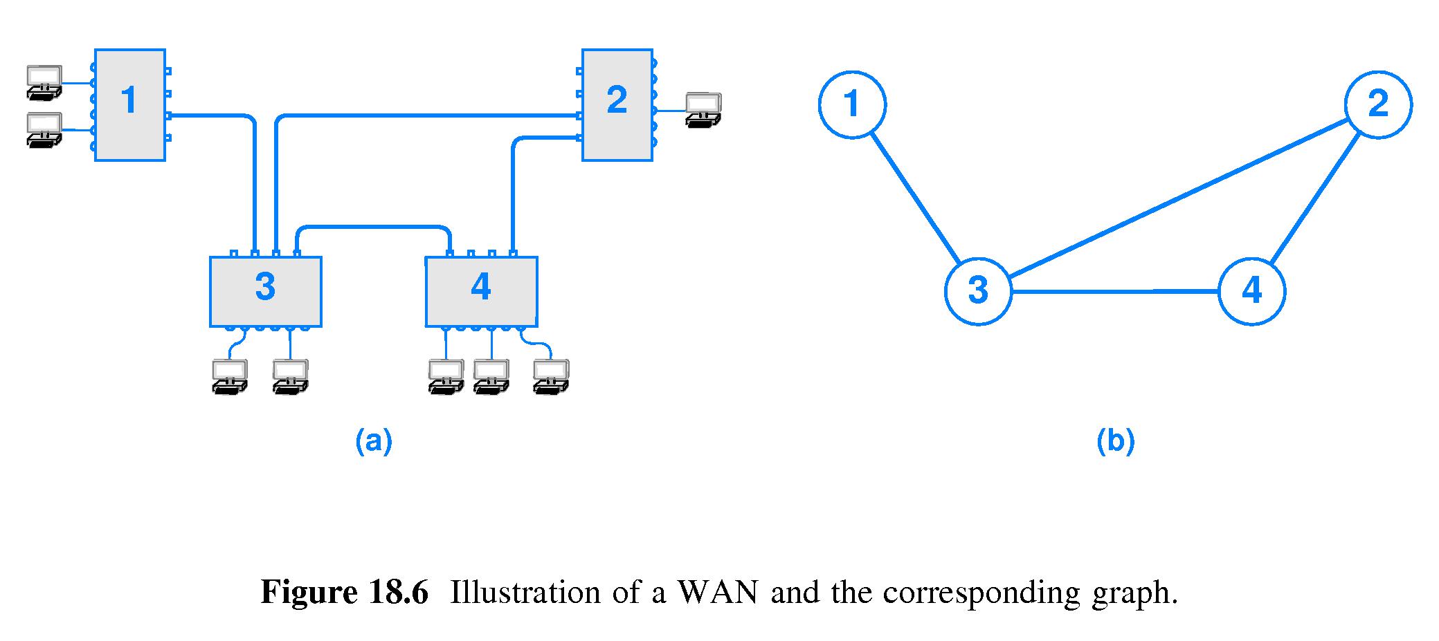
- 18.4 Forming a WAN
- WANs are designed, taking into account required capacity, data rates,
distances spanned, redundancy required, and amount of delay that can
be tolerated
- Long-haul connections between sites may be implemented with various
technologies, including wire or fiber leased lines, microwave and
satellite channels.
- Designers have to choose the topology - they have to
choose which links to establish between sites.
- 18.5 Store and Forward Paradigm
- To support simultaneous communication to an optimal degree,
packet switches use a store and forward paradigm.
- Packet switches have memory, and the ability to temporarily store
packets they have received in their memory.
- When a switch receives a packet, it is not required to forward it
to another interface immediately. If the interface is busy, the
switch can temporarily store the packet in a queue in memory.
- Because of the ability of packet switches to queue (to buffer)
packets, senders do not have to wait for each packet to be forwarded
by the switch before sending another packet to the switch.
Therefore, overall utilization and performance of the network is
supported.
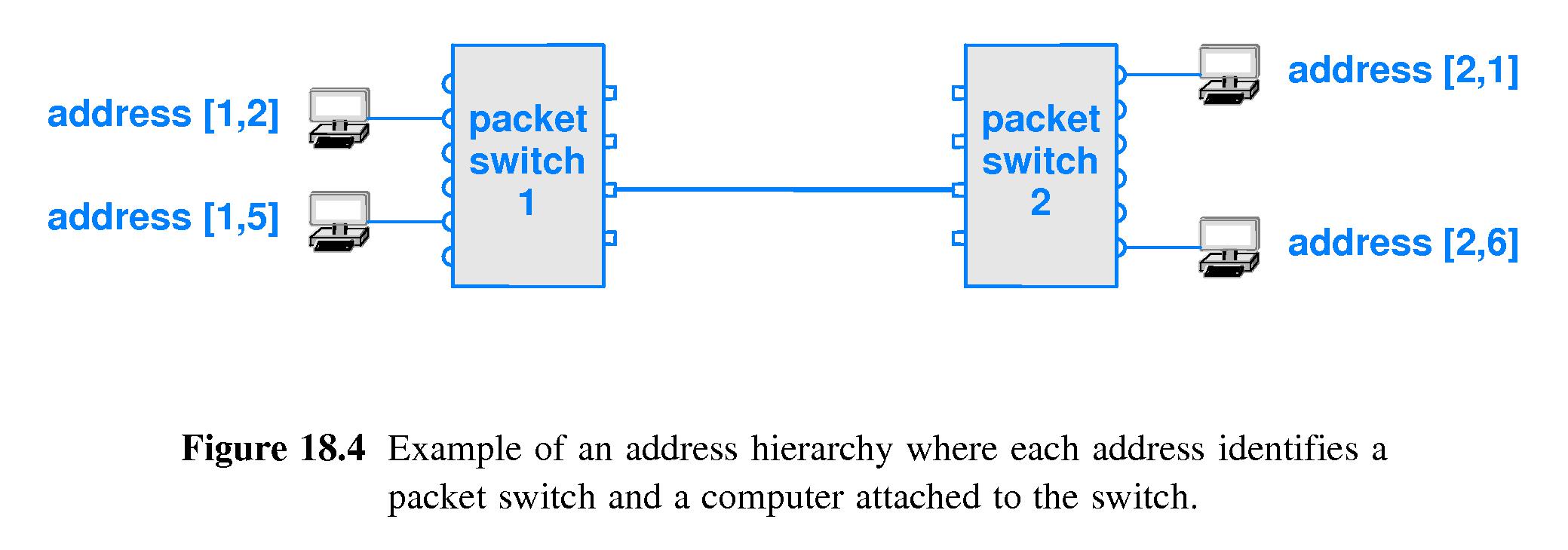
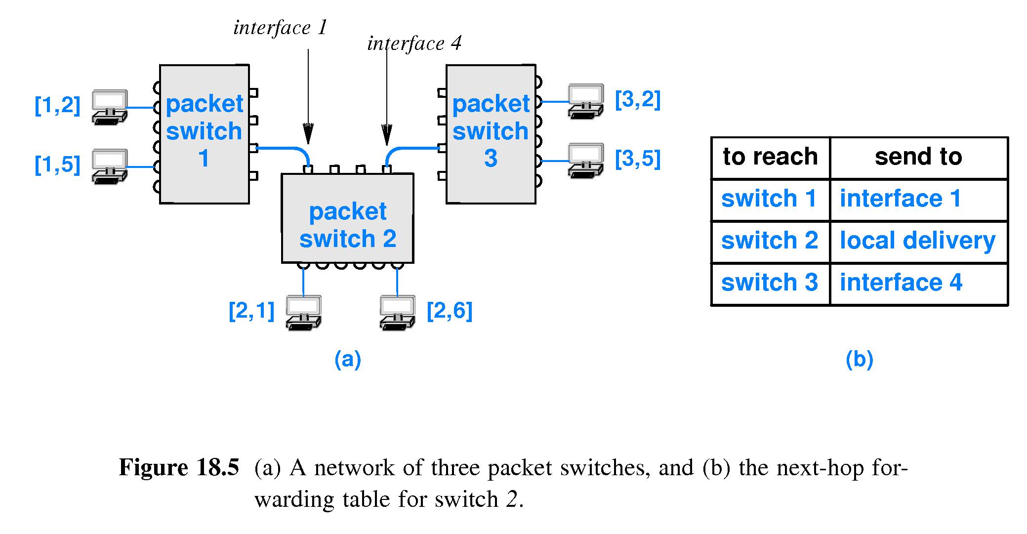
- 18.6 Addressing in a WAN
- In a WAN, typically computers have hierarchical addresses -
two-part addresses. One part designates the packet switch to which
the computer is attached and the other part designates which one
of the computers directly attached to the switch.
- The addressing scheme used for the Internet uses essentially
the same idea.
- 18.7 Next-Hop Forwarding
- Refer to Algorithm 18.1 on page 311 of the sixth edition.
- Packet switches use forwarding tables or the equivalent, to
determine how to route packets.
- When a packet arrives at a switch, the switch extracts the first part
of the destination address (basically the destination switch number).
If the destination switch is not the local switch, the packet
needs to be forwarded, so the switch does a table lookup
to determine the next hop interface - the outgoing connection
on which to send the packet so that it can be sent to the next switch
along the path it is supposed to take through the network.
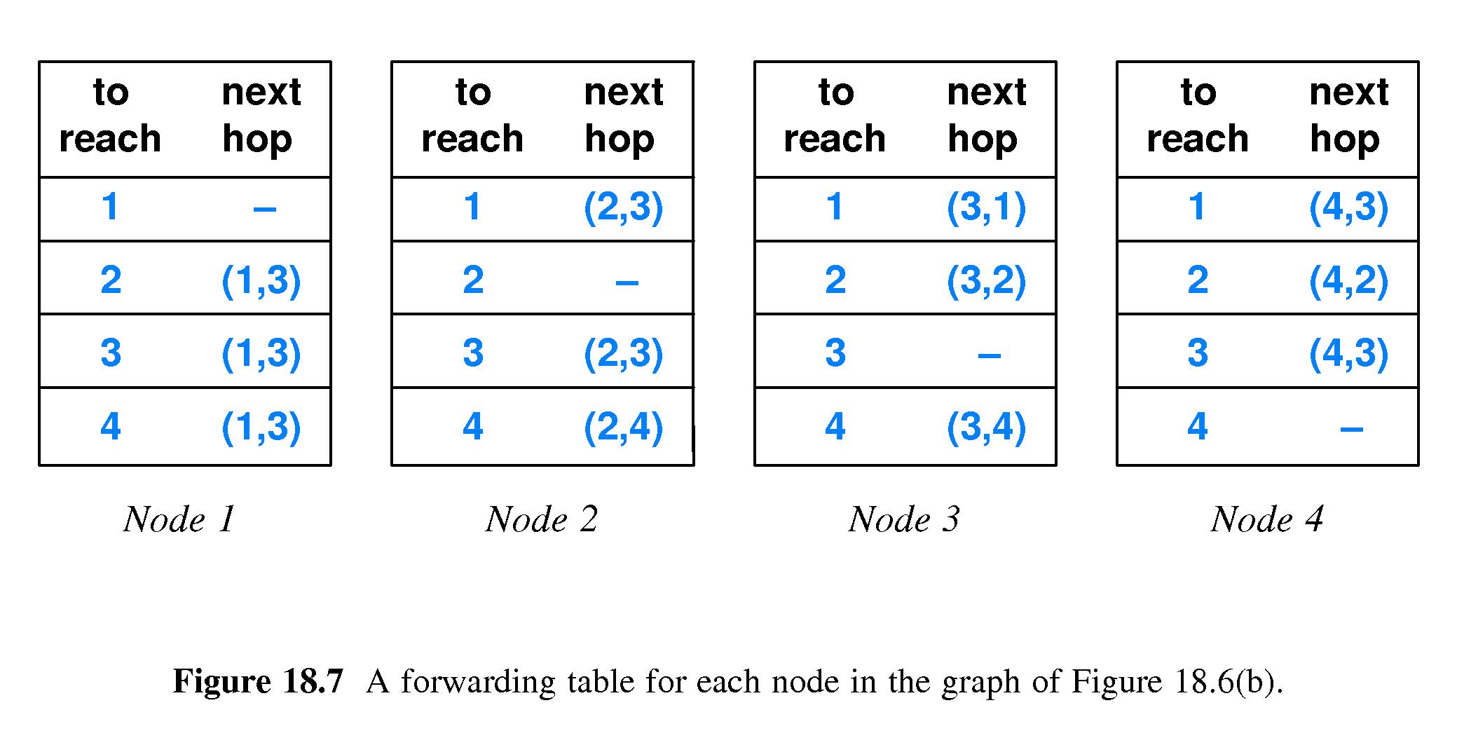
- The next-hop forwarding table only needs one entry for each
packet switch - not individual, per-destination-computer entries.
- Note that each packet switch is concerned only with how to determine
a packet's next hop. Packet switches don't need to keep track of
entire pathways that packets follow.
- If switch number X receives a packet with a destination address of
the form (X,Y), the switch looks up Y in a table or uses some other
means to determine on which local interface to transmit the packet.
This is how the packet is routed locally to the NIC that is its final
destination.
- 18.8 Source Independence
- Next-hop forwarding is source independent
- A packet switch bases its forwarding decision solely on the
destination address.
- 18.9 Dynamic Routing Updates in a WAN
- Refer to figure 18.7 on page 314
- Switches are supposed to be able to forward to every possible
destination address.
- Switches are supposed to forward on an interface that provides
a 'shortest' route.
- Because links between packet switches can go up and down, typically
routing software continually monitors the network graph and
updates the forwarding tables.
- The job of routing software is to insure that collectively the packet
switches route packets along the shortest paths currently available
between source and destination.
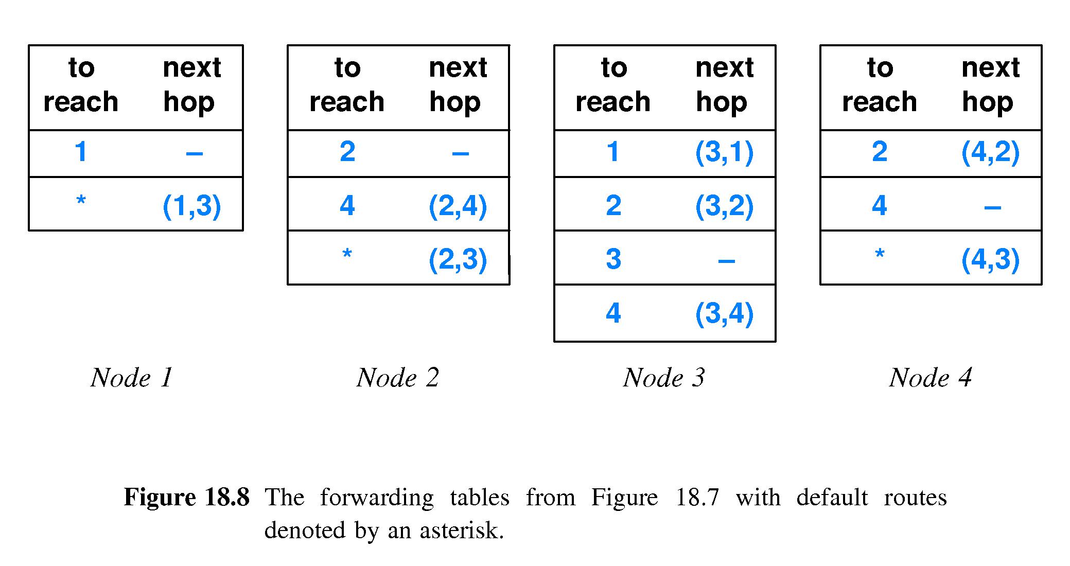
- 18.10 Default Routes
- If many entries of a forwarding table contain the same next hop
designation, say H, one may remove all such entries from the table
and represent them instead as a default route to H.
- To route a packet, first check the remaining part of the table. If
the destination switch number does not match any of those table
entries, then conclude that next hop H is to be used.
- This scheme may cut down drastically on the amount of memory
needed to store the forwarding table.
- 18.11 Forwarding Table Computation
- Static Routing: a program computes forwarding table when the
packet switch boots and it does not change - pros: simple,
low overhead; cons: inflexible.
- Dynamic Routing: like static routing except the program alters
the forwarding tables as network conditions change. Most WANs use
some form of dynamic routing. pros: flexible
adaptation of routes; cons less simple & more overhead.
- 18.12 Distributed Route Computation
- Refer to algorithm 18.2 on page 317 of edition six
- Refer to algorithm 18.3 on page 319 of edition six
- Each packet switch must compute its own routing table (locally).
- Link-State Routing and
Distance-Vector Routing are two general
approaches to distributed route computation.
- 18.12.1 Link-State Routing (LSR)
- Link-State Routing (LSR) - aka Link-Status Routing - aka
Shortest Path First (SPF) routing
- Packet switches periodically broadcast (to all other reachable
packet switches) information they know about which links are up
or down (e.g. "A link between switches 5 and 9 is up" or "The
link between switches 3 and 12 is down").
- Using this information software running on each packet switch
maintains and updates a representation of a graph showing all
links known to be up, and the packet switches connected to them.
- Each time it updates the graph, the software next uses Edsger
Dijkstra's "all nodes, shortest paths" algorithm to (re-)
compute the shortest possible paths between itself and all the
other reachable packet switches.
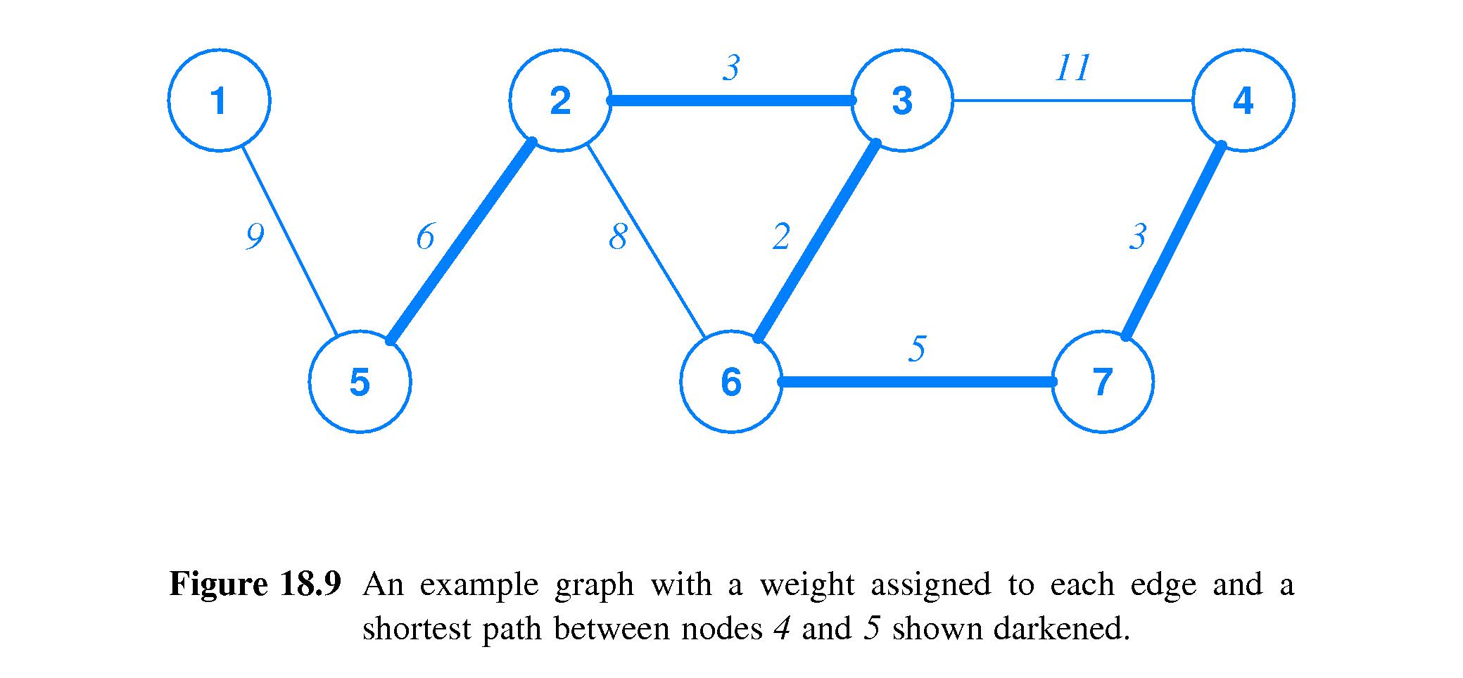
- The algorithm assigns a 'weight' to each link - some number
that indicates the relative amount of delay or other cost of
traversing the link. "Shortest path" means "path with least
total weight.
- After it computes a new shortest-path, the software on the
packet switch updates, if necessary, the next-hop entry of its
forwarding table corresponding to the endpoint of the new path.
- 18.12.2 Distance Vector Routing
- Periodically a packet switch sends a (DVR) message to all the
other packet switches to which it is directly connected.
- The contents of a message is a list of items of this form:
"I can reach destination X, and its current distance from me is
Y"
The list sent by a packet switch S contains such an item for
every other packet switch that S can reach.
- This information is not broadcast. None of the adjacent switches
forwards these messages. They just pass between packet switches
and their directly-connected neighbors.
- When a packet switch M receives a DVR message from a neighbor N,
it can use the information in various ways to update its
forwarding table. (See algorithm 18.3 on page 319.)
- 18.13 Shortest Paths and Weights
- Dijkstra's algorithm may be used with different definitions of
weight.
- Sometimes each connection between packet switches is assigned a
weight of 1.
- Sometimes weights are inversely proportional to link capacity.
- Weight can indicate expected delay along a link.
- Sometimes high weights are assigned by network managers to discourage
use of the corresponding links.
- 18.14 Routing Problems
- Routing problems can occur if Link State Routing messages are lost or
if a packet switch receives DVR messages that it sent.
- Problems with DVR can be more severe - e.g. routing loops.
- Routing systems in actual operation have safeguards against potential
errors, but problems sometimes do occur.