- Be able to explain the basics of why multiplexing is needed, how multiplexing works, and what multiplexors and demultiplexors do.
- Be able to explain the key ideas of FDM, WDM, TDM, and CDM
- Be able to describe the idea of statistical TDM
- Be able to describe the need for _inverse_ multiplexing, how it works, and what inverse multiplexors and inverse demultiplexors do
11.1 Introduction
- Motivation for multiplexing
- Basic types of multiplexing
- Basis provided by modulated carriers
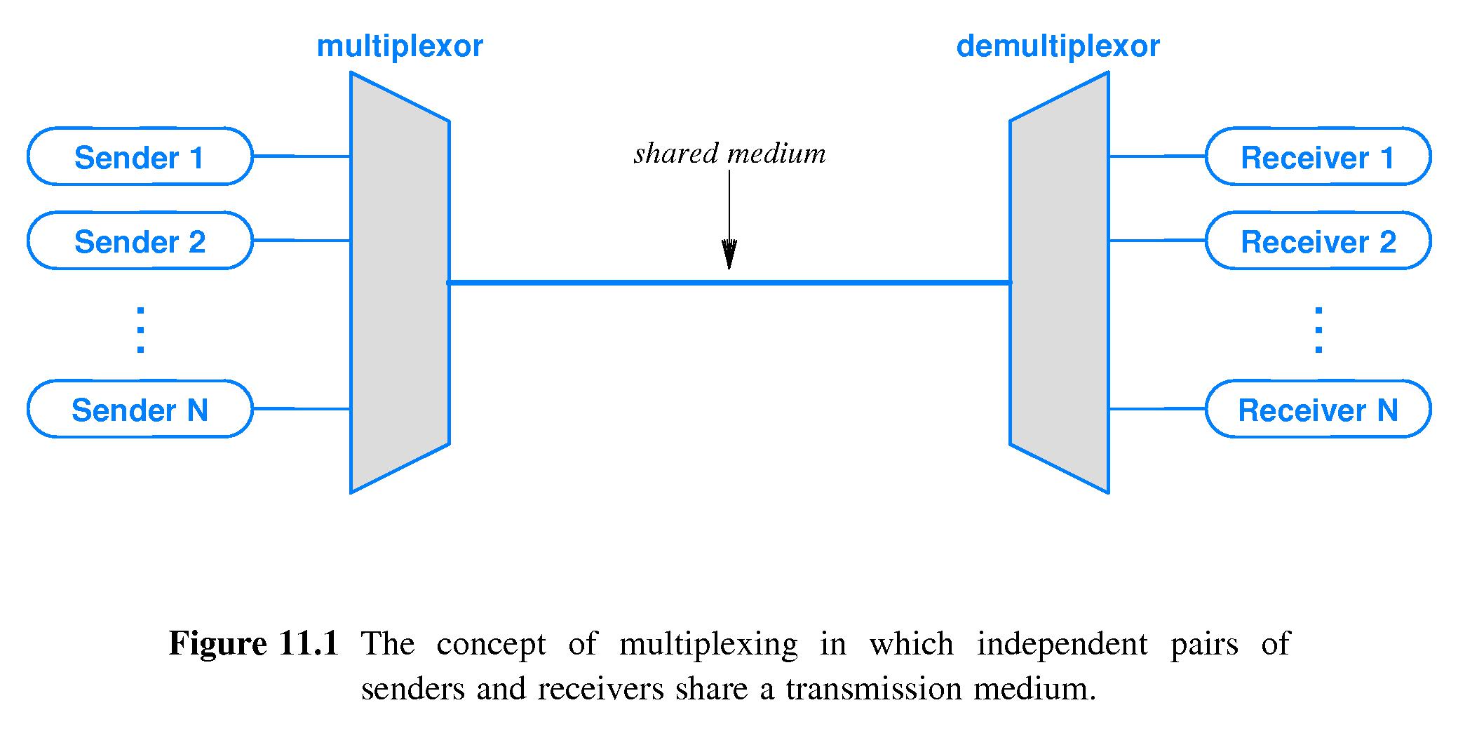
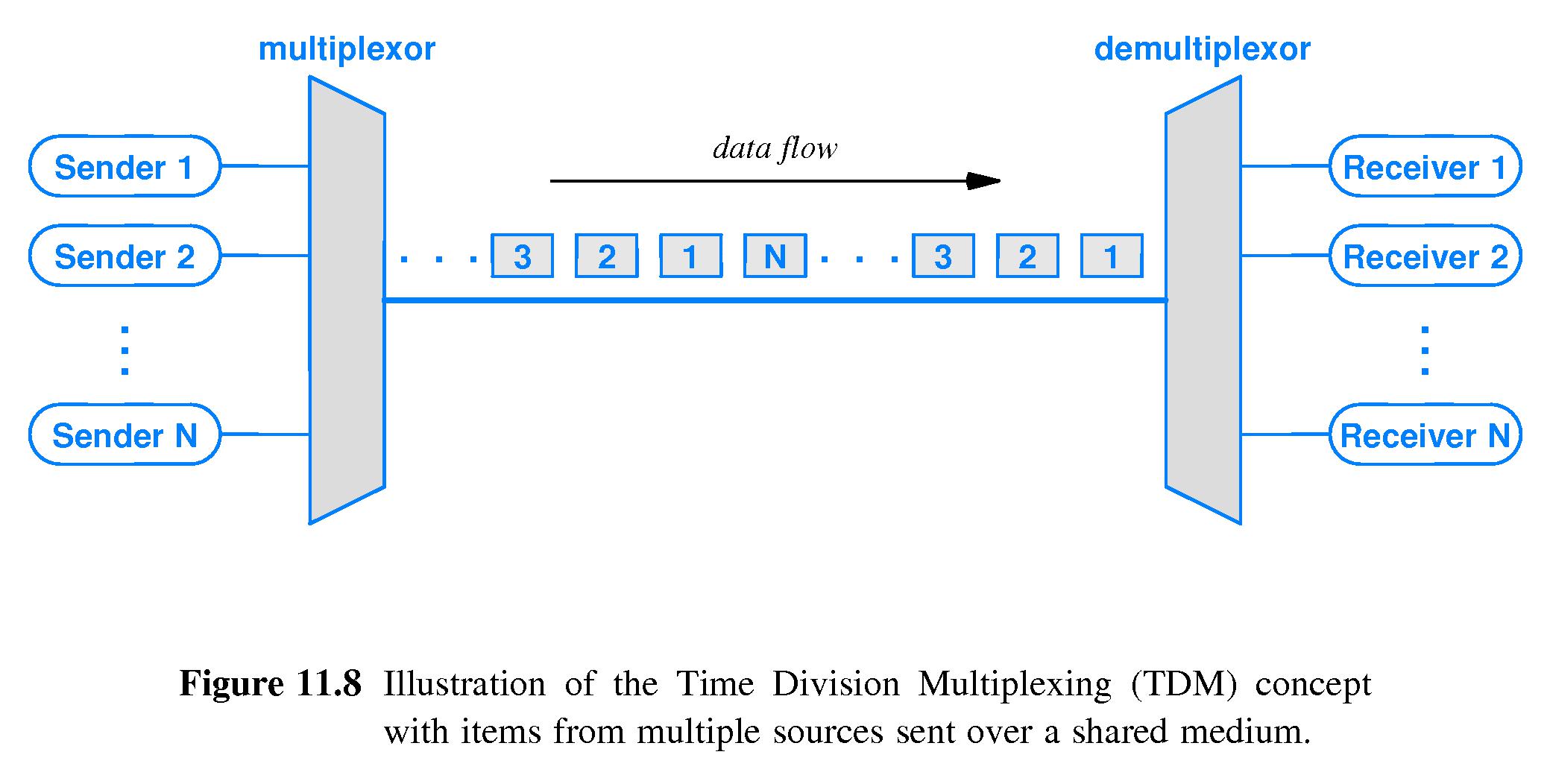
- Multiplex: to combine information streams from multiple sources for the purpose of transmitting them over a shared medium.
- Multiplexor: a device that performs multiplexing
- Demultiplex: to separate information that has been multiplexed back into its constituent information streams.
- Demultiplexor: a device that performs demultiplexing
- Frequency Division Multiplexing (FDM, widely used)
- Wavelength Division Multiplexing (form of FDM used with fiber)
- Time Division Multiplexing (TDM, widely used)
- Code Division Multiplexing (cell phone mechanisms)
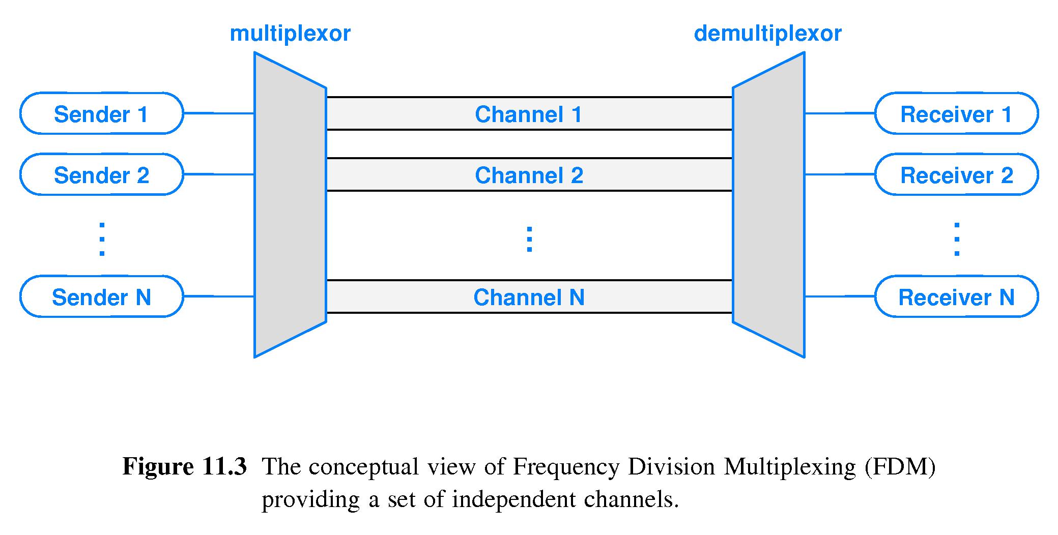
- FDM is the familiar idea of "channels" in radio and television.
- The idea of FDM is to use multiple carriers of different frequencies simultaneously on a medium like a copper wire or optical fiber (or to broadcast through the air with RF as with radio and tv)
- Demultiplexors use filters to select a small range of frequencies
near just one of the carrier frequencies, and suppress other
frequencies.
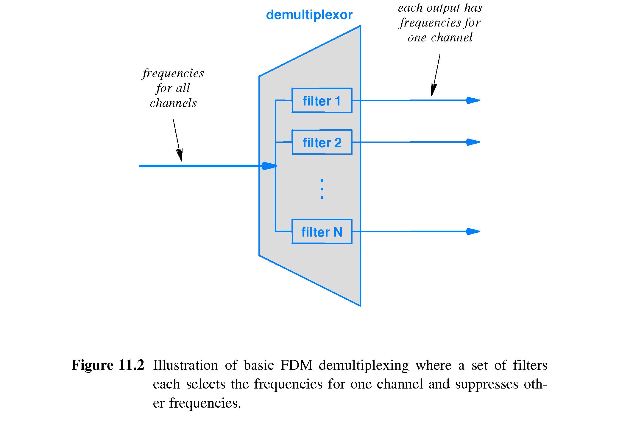
- Any modulation scheme can be used on each carrier.
- Carrier frequencies that are too close are difficult for
a demultiplexor to separate, and they can interfere with each other.
Therefore FDM schemes separate carriers with gaps called
guard bands.
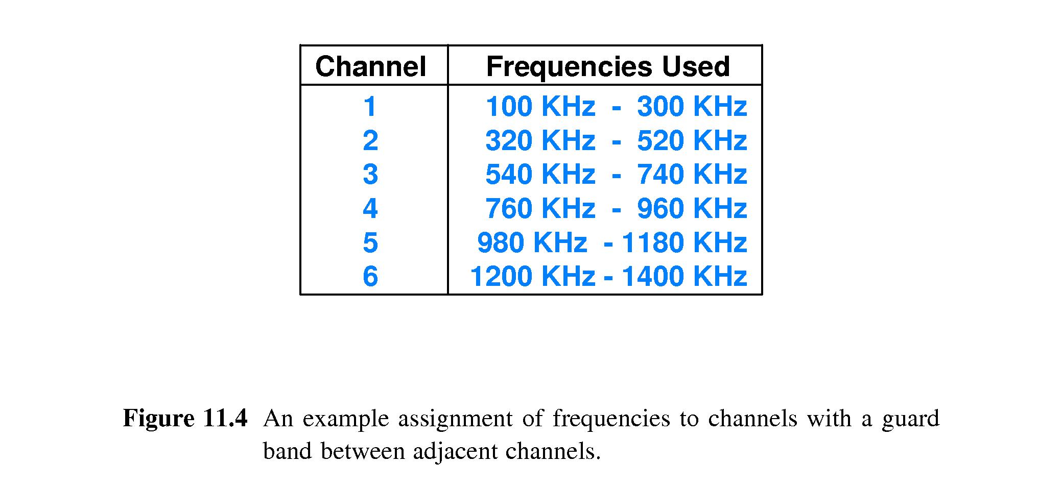

- Carrier 'channels' often contain a relatively wide range of frequencies.
- Users of the channel can divide it up into K 'sub-carriers' and, to achieve high data rates, send 1/K of the data over each carrier.
- To increase immunity from interference, a sender can transmit the same information over several 'sub-carriers' and give the receiver the option to use the ones that experience the least interference. This is the basic idea of spread spectrum.
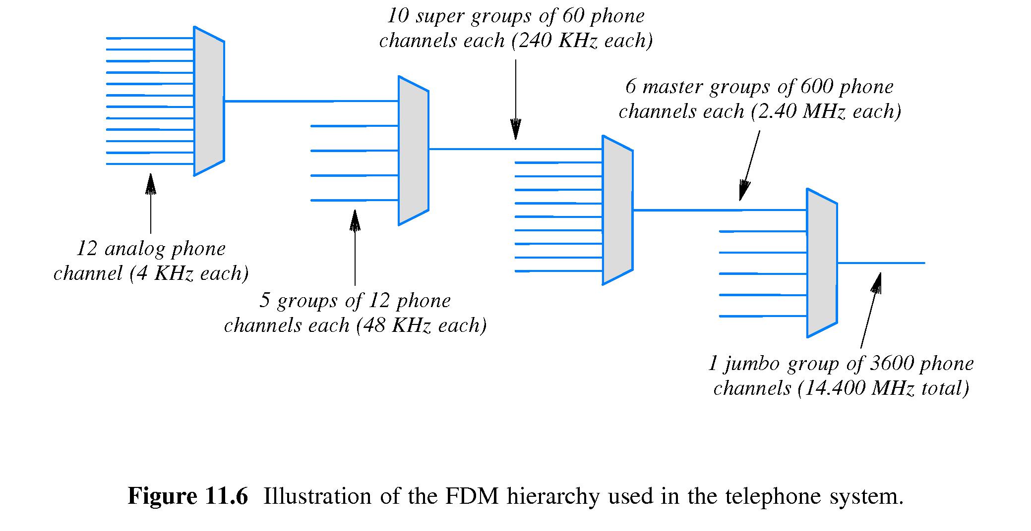
- By using outputs of some multiplexors as inputs to other, it is possible to cause large numbers of individual communication streams to flow into a single shared medium supporting a very large number of data streams.
- This technique is used in telephone systems - e.g. 3600 telephone channels together on one 14,400 Hz signal band.
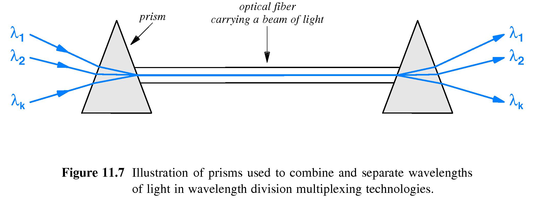
- In the case of optical fibers, multiplexors and demultiplexors use prisms.
- This is the idea of wavelength division multiplexing (WDM)
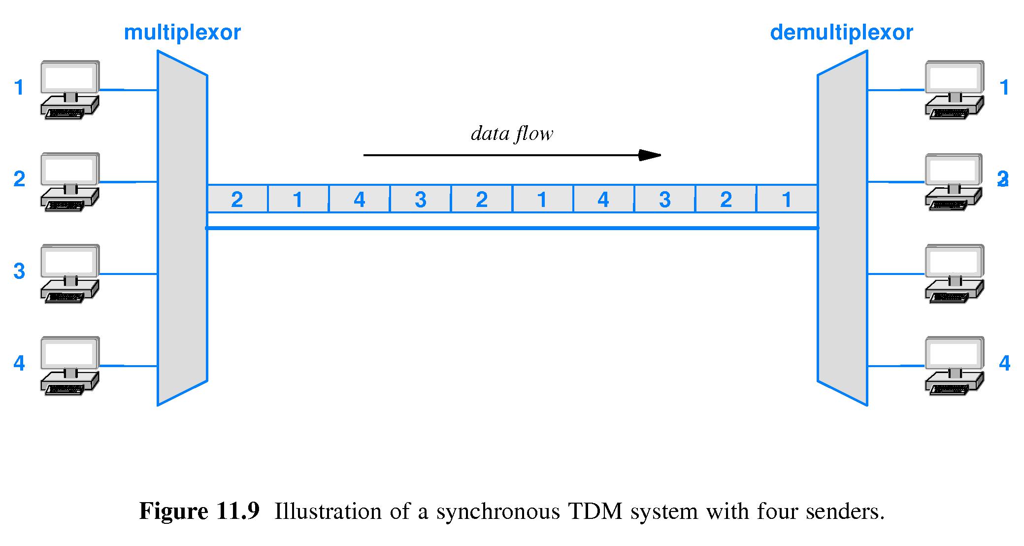
- TDM is the main alternative to FDM.
- Basically TDM is just 'taking turns' using the shared medium.
- Round robin sharing may or may not be used with TDM
- On synchronous networks, TDM performs round robin sharing and there are no gaps between items sent.
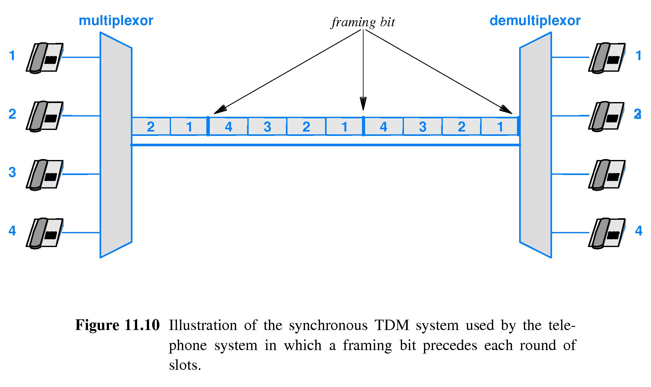
- The telephone company TDM scheme adds an extra framing channel and alternating framing bits to help the demultiplexor stay synchronized or (at least) detect errors.
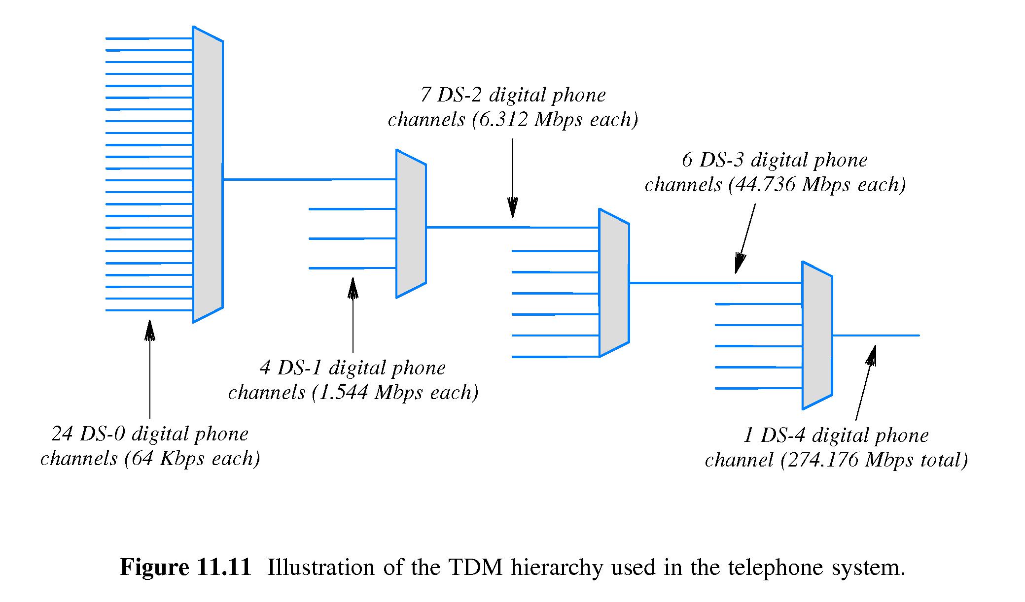
- Hierarchical TDM works similarly to hierarchical FDM.
- At a stage where there are N inputs of bit rate R, one needs the output bit rate to be no less than NR.
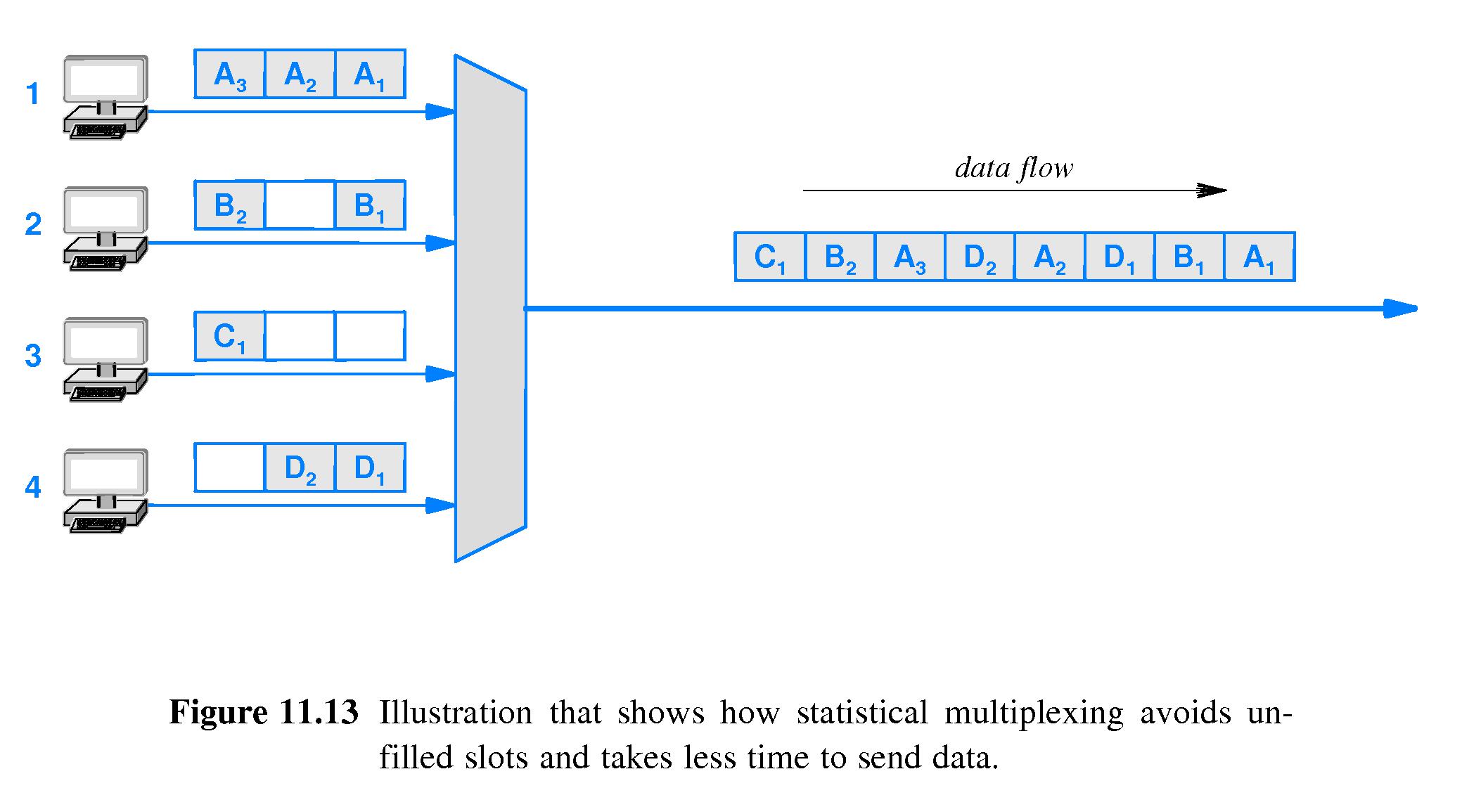
- Under a 'vanilla' form of TDM, if a source has nothing to send when its time arrives, an "empty slot" is sent - probably a zero-filled block with some sort of invalid flag included.
- Thus capacity is wasted if sources don't always have data ready when it is their turn.
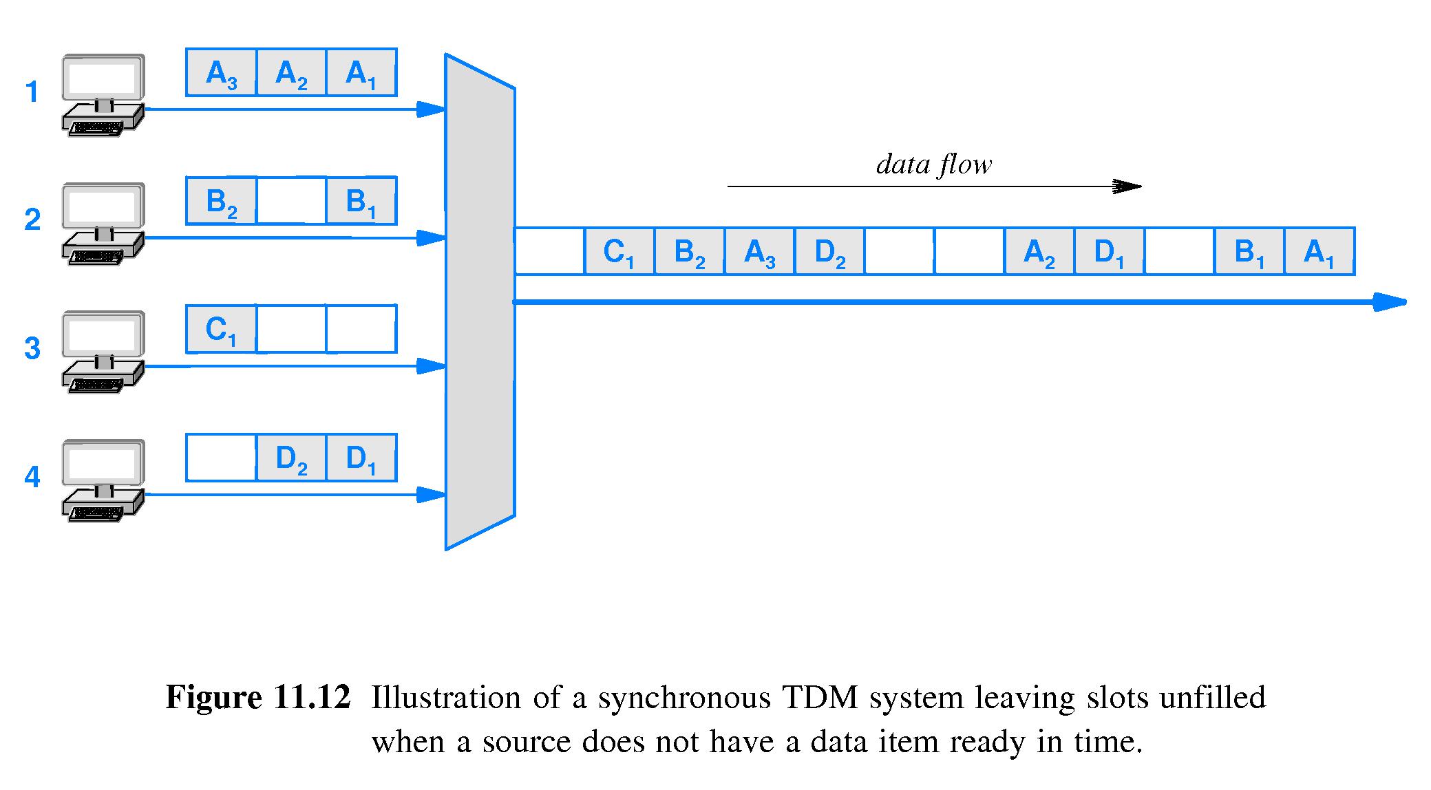
- In a statistical TDM scheme, the multiplexor tries to skip over senders that don't have data ready until coming to one that has data.
- For this to work, the data blocks have to contain something that identifies the intended receiver, else there'd be no way for the demultiplexor to decide to which output stream to assign the data.
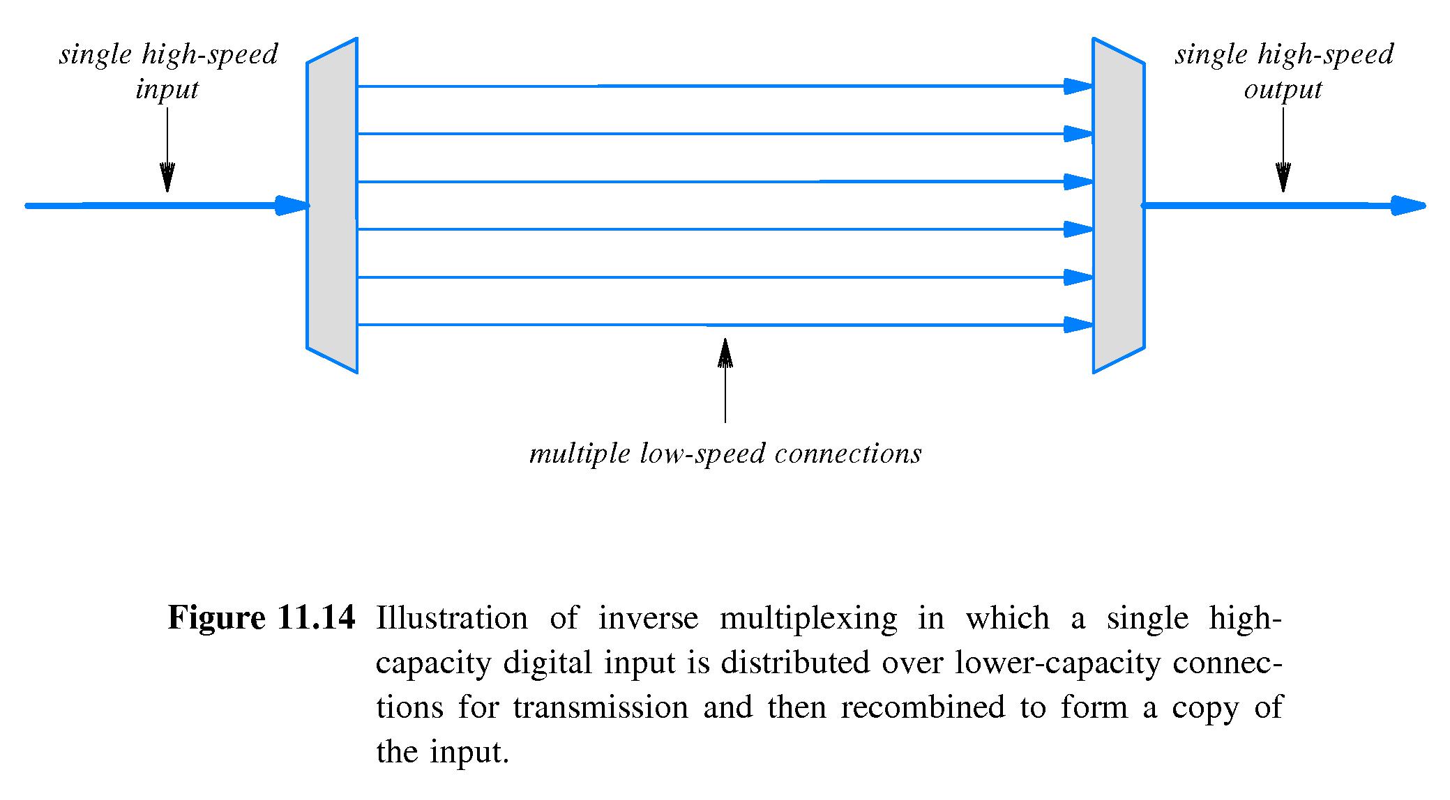
- The idea is to distribute a single high-speed digital input over multiple lower-speed channels, transmit over the multiple channels, and reassemble the original digital signal at the receiving end.
- This is somewhat difficult to engineer.
- The scheme is used widely on the Internet.
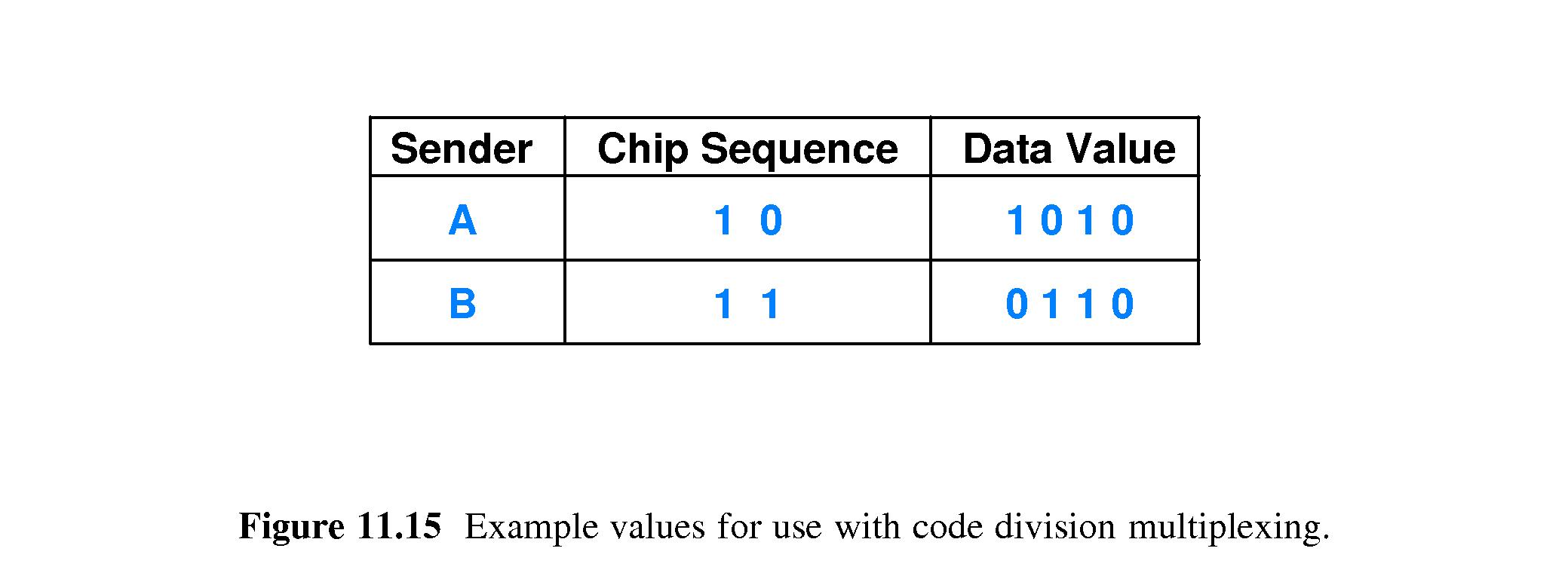
- CDM is the idea behind the CDMA used with cell phones.
- People who have studied vector spaces may understand the scheme more readily.
- The basic idea is actually a lot like doing TDM on a bit level.
- Each sender has a code called a chip sequence
- The chip sequence represents a vector.
- All the vectors determined by chip sequences are mutually orthogonal.
- In effect senders multiply their messages times their chip sequence and send the results to the multiplexor.
- The multiplexor adds the individual inputs from the senders and transmits the sum.
- The demultiplexor uses orthogonal projection - it projects the sum onto each chip sequence to recover one bit of the message from each phone.
- The scheme has some overhead that makes it less efficient than ordinary TDM if utilization is low.
- However, if utilization is high it has the advantage of lower delay. It is basically bit-at-a-time TDM, so phones are delayed only about as long as it takes all the other phones in use to send one bit - rather than the time it would take them to send large blocks of data.