- Describe the physical structure of various secondary storage devices and the effect of a device's structure on its uses.
- Explain the performance characteristics of mass-storage devices
- Evaluate I/O scheduling algorithms
- Discuss operating-system services provided for mass storage, including RAID
-
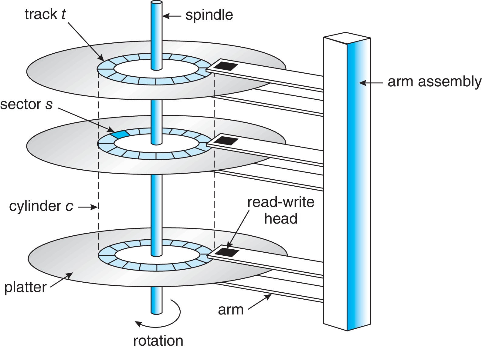
11.1.1 Hard Disk Drives
- Terms to know: platter, disk head, disk arm, track, sector, cylinder, transfer rate, RPM, positioning time (random access time), seek time, rotational latency, head crash
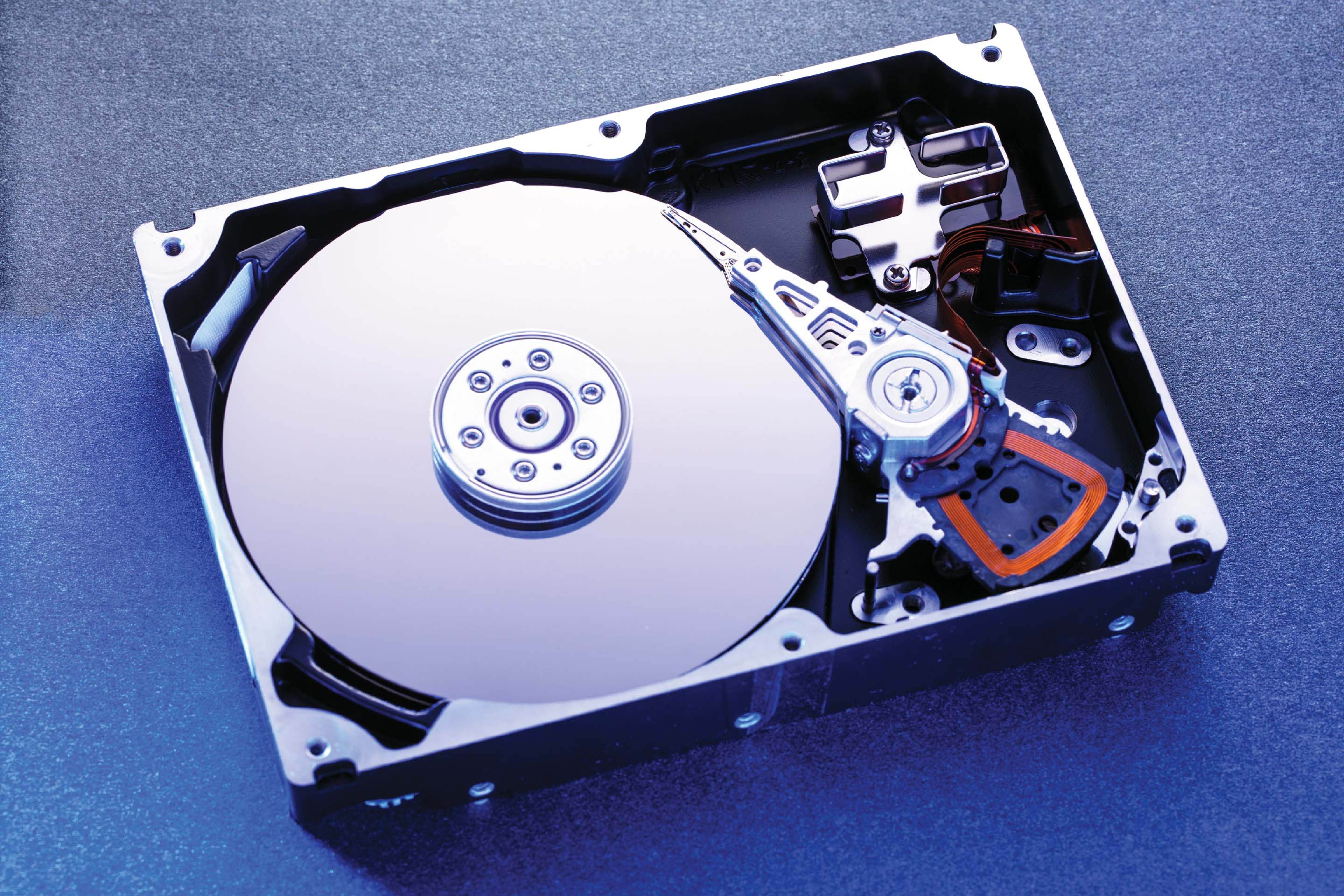
Figure 11.2: A 3.5-inch HDD with cover removed -
11.1.2 Nonvolatile Memory Devices - growing in importance
-
11.1.2.1 Overview of Nonvolatile Memory Devices
- Terms to know: NVM device, solid-state disk (SSD), USB drive
- NVMs are usually made from a controller and NAND die semiconductor chips
- Non-volatile memory used like a disk drive
- Advantages over magnetic disks
- Reliable - no moving parts
- Faster - no seek or latency time (bus may limit throughput)
- Consume less power
- Smaller and lighter
- Disadvantages compared to magnetic disks
- More expensive
- Less capacious
- (maybe) Shorter life due to "write wear"

Figure 11.3: A 3.5-inch SSD circuit board -
11.1.2.2 NAND Flash Controller Algorithms
- (Some details here about managing the technology,
which does not support simple over-writing)

Figure 11.4: A NAND block with valid and invalid pages
- (Some details here about managing the technology,
which does not support simple over-writing)
-
11.1.2.1 Overview of Nonvolatile Memory Devices
-
11.1.3 Volatile Memory
- RAM drives can be used as raw block devices or for filesystems
- Useful as fast temporary file systems
-
Magnetic Tapes
- Non-Volatile
- Capacious
- Slow Access Time
- Mainly for backup, storage, and transfer
- Once positioned, can read/write at speeds comparable to disk
- "Never underestimate the bandwidth of a station wagon full of tapes hurtling down the highway." -- Tanenbaum, Andrew S. (1989). Computer Networks. New Jersey: Prentice-Hall. p. 57. ISBN 0-13-166836-6.

Figure 11.5: An LTO-6 Tape drive with tape cartridge inserted -
11.1.4 Secondary Storage Connection Methods
- Bus Technologies: advanced technology attachment (ATA), serial ATA (SATA), eSATA, small computer systems interface (SCSI), serial attached SCSI (SAS), universal serial bus (USB), fibre channel (FC)
- Busses tend to be a bottleneck for NVMs so there is an NVM express (NVMe) bus technology.
- There are host controllers on the computer end of the bus, and device controllers built into each storage device.
- To perform I/O, operating system drivers place commands into host controllers, and host controllers communicate with device controllers.
- Data transfer commonly happens between the storage media and a cache in the device controller.
-
11.1.5 Address Mapping
- Logical addressing on storage devices treats them as a one-dimensional array of logical blocks.
- The logical block is the smallest unit of transfer.
- Logical blocks are mapped onto sectors or pages of the device.
- "Sector 0 could be the first sector of the first track on the outermost cylinder on an HDD, for example. The mapping proceeds in order through that track, then through the rest of the tracks on that cylinder, and then through the rest of the cylinders, from outermost to innermost."
- For NVM, mapping is from (chip, block, page) to an array of logical blocks.
- On an HDD, it's not really so clear how to figure out the physical address from the logical address, because other sectors are substituted for defective sectors, and also the number of sectors per track is not a constant on some drives, and disk manufacturers internally manage the mapping of logical to physical address.
- Some disk technologies, like CD-ROM and DVD-ROM, have uniform density of bits per track and use constant linear velocity (CLV).
- Hard disks typically have decreasing density of bits from inner to outer track and use constant angular velocity (CAV).
- Numbers of sectors per track and cylinders per disk have been increasing over time, now several hundred sectors per track, and up to tens of thousands of cylinders.
Generally it is useful for an OS to schedule a queue of hard-disk I/O requests. It can help reduce access time and increase the device bandwidth - basically the effective rate of data transfer. In modern devices, it's not possible to know with certainty how logical addresses correspond to physical addresses, but generally algorithms perform well under the assumptions that increasing logical block addresses (LBAs) mean increasing physical addresses, and LBAs close together equate to physical block proximity.
-
11.2.1 FCFS Scheduling
- "Intrinsically fair" but often results in long seeks
Figure 11.6: FCFS disk scheduling
Figure 11.7: SCAN disk scheduling -
11.2.2 SCAN Scheduling: "The Elevator Algorithm"
- Starts at one "end", say the outermost cylinder, and works its way across the disk toward the other end, servicing requests on cylinders as it arrives on the cylinders.
- When it reaches the other end, it starts back in the other direction, continues until arriving back at the start point, and then repeats.
- To avoid starvation, only the requests that were on the cylinder when the head arrived there should be serviced. The rest should wait until the next time the head moves to the cylinder.
- Problem: When the head changes direction, there are not likely to be very many requests waiting on the cylinders it moves to next, because the pending requests there have just been serviced.
Figure 11.8: C-SCAN disk scheduling -
11.2.3 C-Scan Scheduling
- Designed to solve the problem with SCAN Scheduling
- Upon finishing with the innermost cylinder, the head moves immediately to the outermost cylinder, without servicing any of the requests on the cylinders over which it travels. It then begins another sweep from outside to inside, now servicing each cylinder's requests as it arrives there.
-
11.2.4 Selection of a Disk-Scheduling Algorithm
- If the queue is always near empty, FCFS is fine.
- Something like SCAN or C-SCAN is good for devices with heavy loads.
- Linux has a "deadline" scheduler that averts starvation.
- Linux Red Hat 7 has options of a "NOOP" scheduler and a "Completely Fair Queueing" (CFQ) scheduler.
- Disk scheduling algorithms are for hard disks.
- FCFS is about all that's needed for NVMs, with some variation, like merging adjacent writes.
- NVMs are much faster than HDDs at random reads and writes.
- HDDs can sometimes be as fast as NVMs for sequential I/O, especially sequential writing.
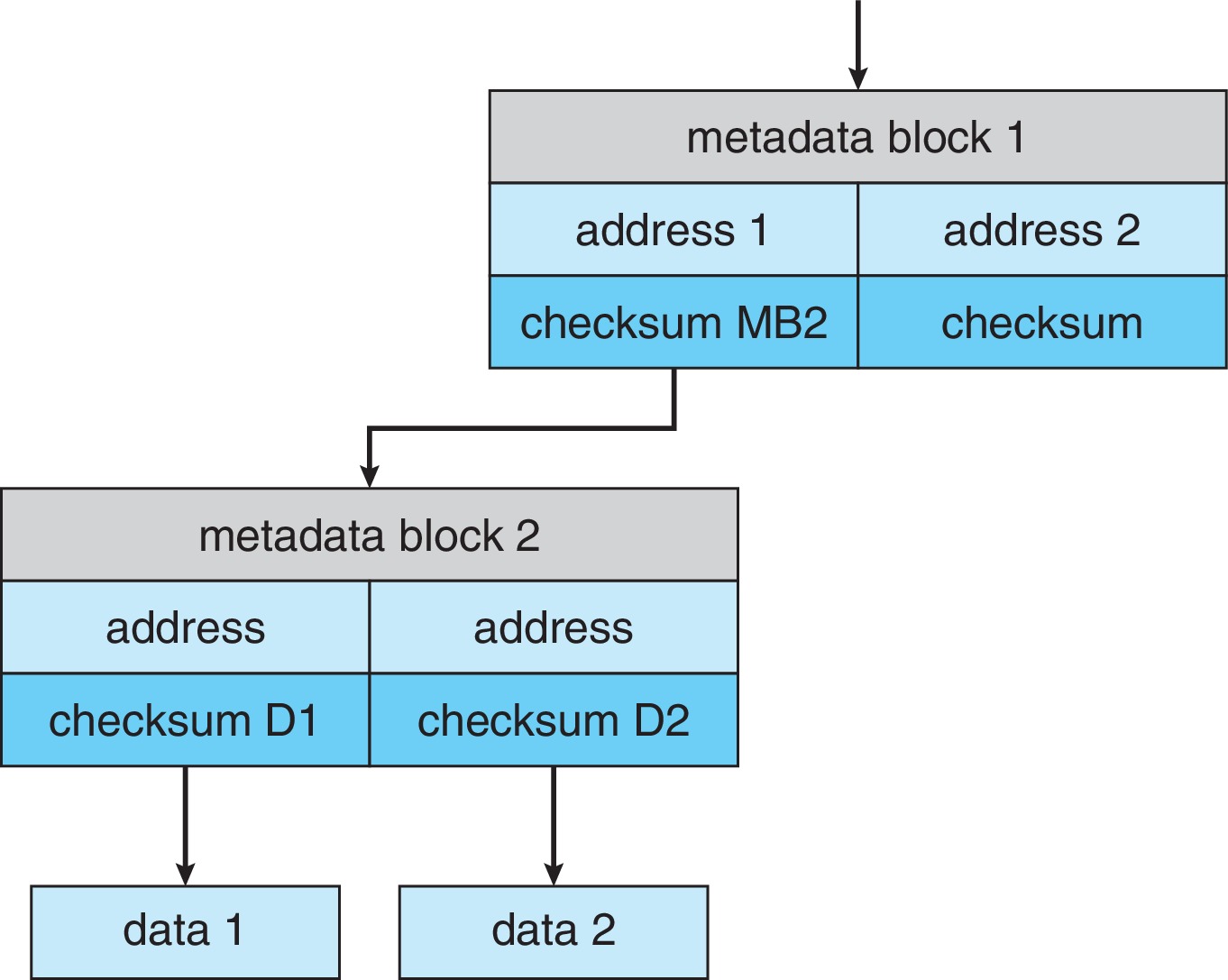
- Forms of error detection: parity bits, checksums, cyclic redundancy checks (CRC), error correcting codes (ECC)
- Concepts: soft error, hard error
-
11.5.1 Drive Formatting, Partitions, and Volumes
- HDDS and NVMs require low-level formatting. On HDDs, low-level formatting divides the tracks into sectors that can be read by the controller - sectors get a header, data area (typically 512 bytes or 4KB), and a trailer. Header and trailer contain sector number and error-correcting code (ECC). It's similar for NVMs.
- Usually the low-level formatting is done at the factory.
- The operating system partitions the device into one or more separate file systems and performs logical formatting to place data structures on the disk that are needed to maintain the file system(s). Examples: free list, and empty top-level directory.
- Sometimes partitions are used "raw" - without any file system structure.
Figure 11.9: Windows 7 Disk Management tool showing devices, partitions, volumes, and file systems -
11.5.2 Boot Block
- Most systems have a bootstrap loader in nonvolatile read-only memory such as NVM flash memory firmware. The bootstrap loader starts executing automatically when the hardware powers up, initializes the hardware, copies a full bootstrap program from disk, and executes it.
- The full bootstrap program resides in "boot blocks" at a fixed location on the secondary storage device. For example, on the first logical block of a hard drive.
- The full bootstrap program copies the OS into primary memory and executes it. Usually a bootstrap program copies the OS from secondary storage, but it could get it from a network server or other source.
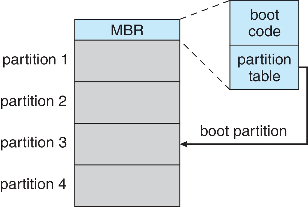
Figure 11.10: Booting from a storage device in Windows
-
11.5.3 Bad Blocks
- It's common for disks to have bad sectors, and for NVMs to have bad bits, bytes, or pages.
- Various methods of detecting bad media and assigning substitutes exist, some more automatic than others.
- Concepts:
- Sector sparing (sector forwarding)
- Sector slipping
- Soft Error
- Hard Error
- In modern systems, swap space is designed to get
good throughput in the paging and swapping done by
the virtual memory subsystem.
-
11.6.1 Swap-Space Use
- Sometimes swap space is needed to back up whole processes, sometimes just for subsets of their pages.
- The relative amounts of swap space needed can vary significantly, as a function of the amount of physical memory, amount of virtual memory, and differences in how virtual memory is used.
- Allocation of sufficient swap space can be critical.
- If a system runs out of swap space, it may have to kill processes, or even crash.
-
11.6.2 Swap-Space Location
- Usually it's best to locate swap space on a secondary memory device separate from where the file systems are located, which makes for better throughput.
- For the same reasons, it can be helpful to have multiple swap spaces located on separate devices.
- Swap files are generally inefficient, due to the need to traverse file system structures in order to use the swap file, and possibly other factors.
- The use of raw partitions for swapping is typically quite efficient.
-
11.6.3 Swap-Space Management: An Example
- At one time it was common to back up whole processes in swap space.
- Now program text is usually just paged from the file system, and swap space is mostly for anonymous memory, such as stacks, heaps, and uninitialized data.
- It also used to be common to preallocate all the swap space that might be needed by a process at the time of process creation.
- Nowadays, systems tend to have abundant primary memory.
They do less paging. On such systems, it
is more common for swap space to be allocated
only as the need for it arises - when pages need to be
swapped out. Skipping the initial swap space allocation
helps processes to start up more quickly.
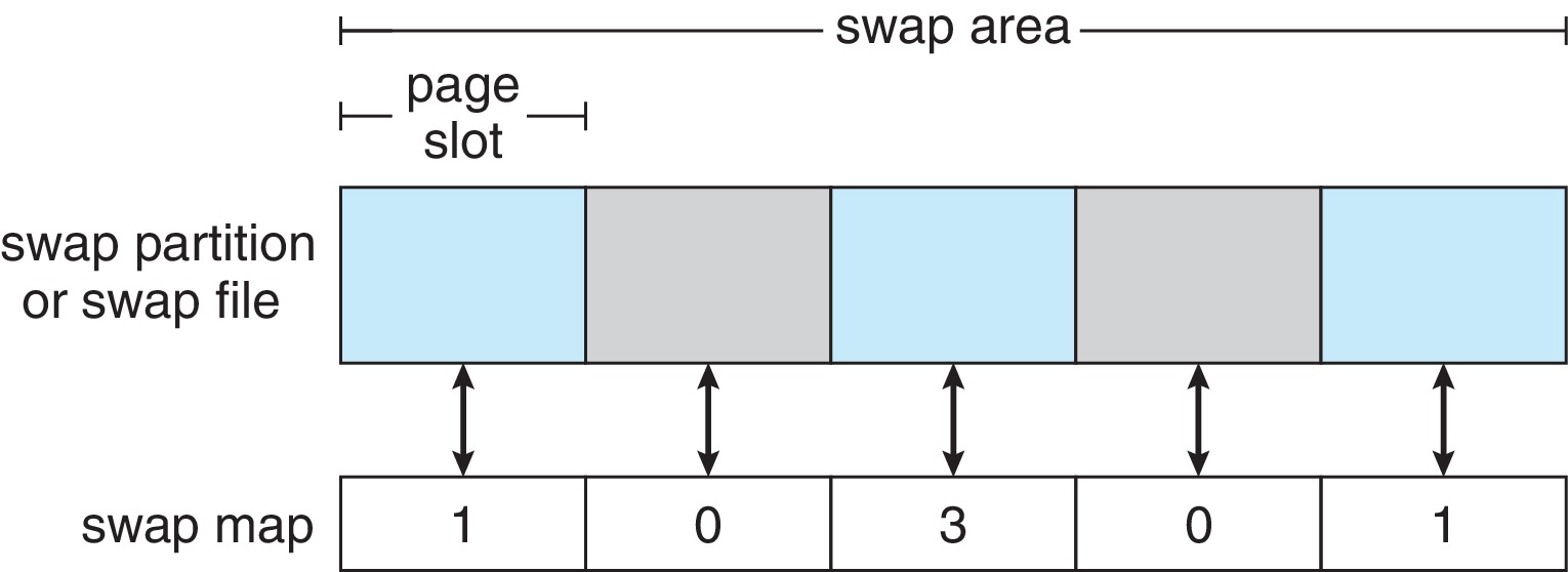
Figure 11.11: The data structures for swapping on Linux systems
-
11.7.1 Host-Attached Storage
- "Host-Attached" means accessed through local I/O ports
- Types of ports: SATA, USB, FireWire, Thunderbolt, Fiber Channel (FC)
- Types of devices: HDDs; NVM devices; CD, DVD, Blu-ray, and tape drives; and storage-area networks (SNA)
-
11.7.2 Network-Attached Storage
- Accessed remotely over a data network, typically via an RPC-based interface (unix NFS or Windows CIFS) using TCP or UDP network protocols
- Typically implemented as a RAID array
- Allows multiple computers in a network to share storage
- Network-attached storage tends to be less high-performance than host-attached
- iSCSI is the latest protocol. Essentially it uses the IP network protocol to carry the SCSI protocol.
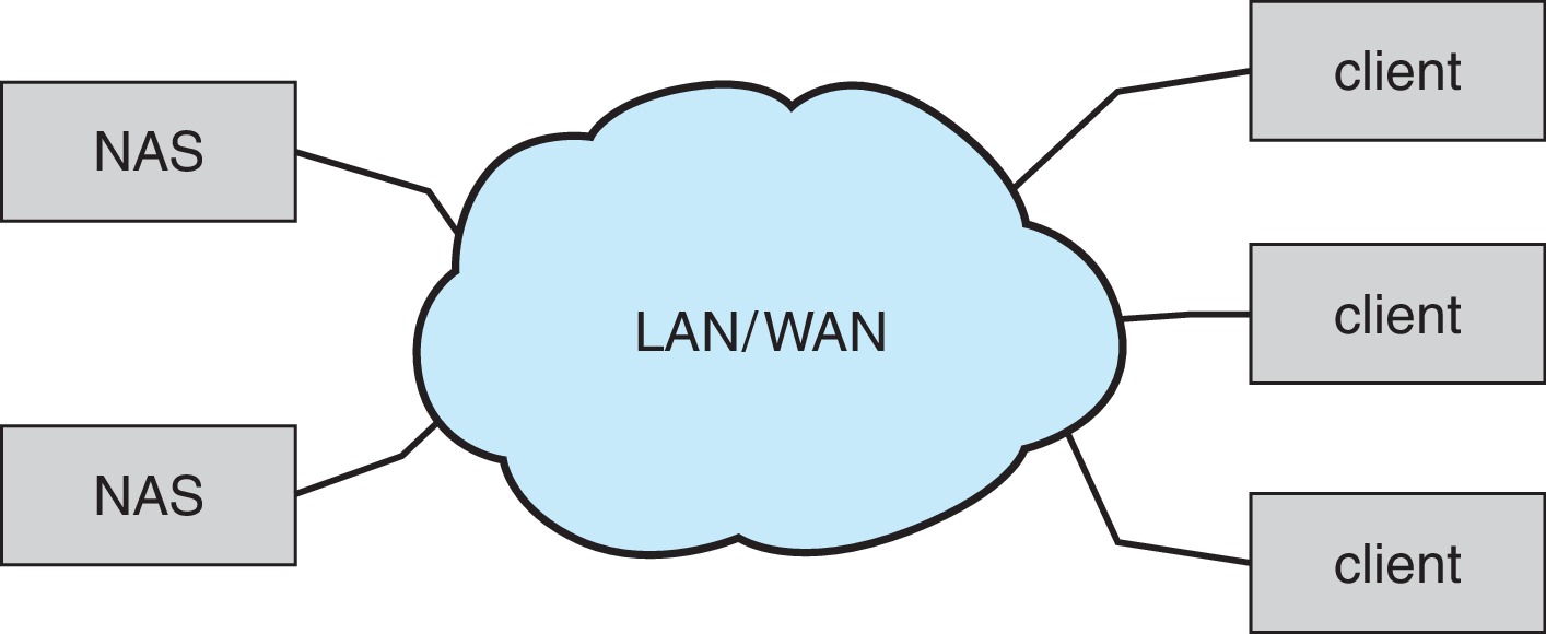
Figure 11.12: Network-attached storage -
11.7.3 Cloud Storage
- Similar to network-attached storage (NAS), but accessed over the Internet or another wide area network (WAN)
- Cloud storage is not usually accessed as "just another file system" like NAS, but accessed using an API.
- The use of APIs works well with the latency and failure scenarios on a WAN.
- Examples: Amazon S3, Dropbox, Microsoft OneDrive, Apple iCloud

Figure 11.13: Storage-area network -
11.7.4 Storage-Area Networks and Storage Arrays
- Like Network-attached but uses a separate, private, network for the connections between hosts and storage. Thus it avoids contention with traffic on the data communication network
- Utilizes special storage protocols on its network
- Multiple hosts and multiple storage arrays may attach to a common SAN.
- Settings on a SAN switch determine which hosts can access which storage arrays.
- SANs are high-performance.
- Interconnect technologies: FC, iSCSI, InfiniBand

Figure 11.14: A storage array
- Redundant arrays of independent (formerly: inexpensive) disks (RAID) can provide higher data reliability and data-rate transfer.
- 11.8.1 Improvement of Reliability via Redundancy
-
11.8.2 Improvement in Performance via Parallelism
- data striping, bit-level striping, block-level striping
- Striping provides high data-transfer rates.
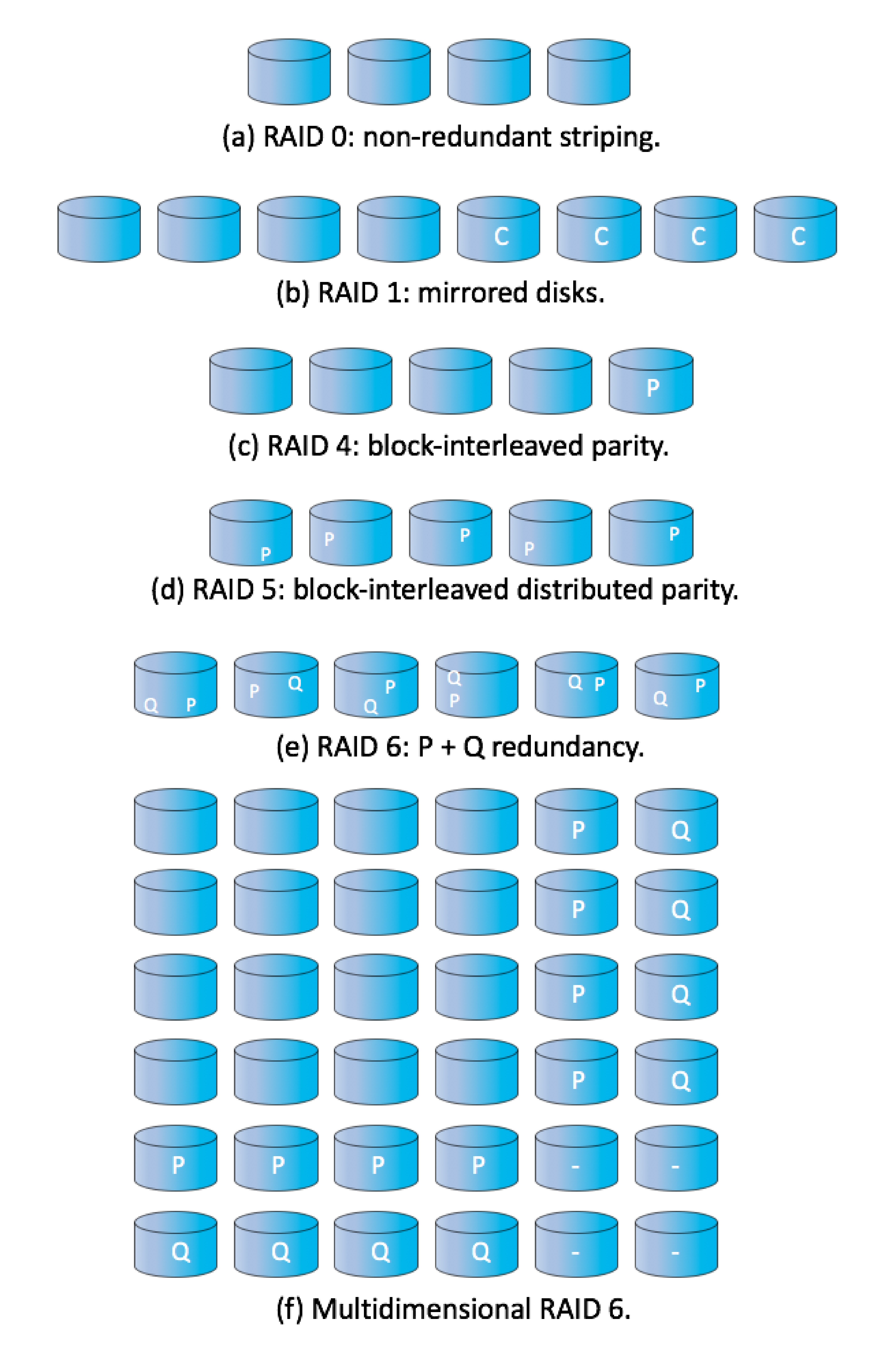
Figure 11.15: RAID levels -
11.8.3 RAID Levels
- Various RAID levels utilize 'parity bits' and/or mirroring with striping to achieve both high reliability and high data-transfer rates.
- RAID level 0
- RAID level 1
- RAID level 4
- RAID level 5
- RAID level 6
- Multidimensional RAID level 6
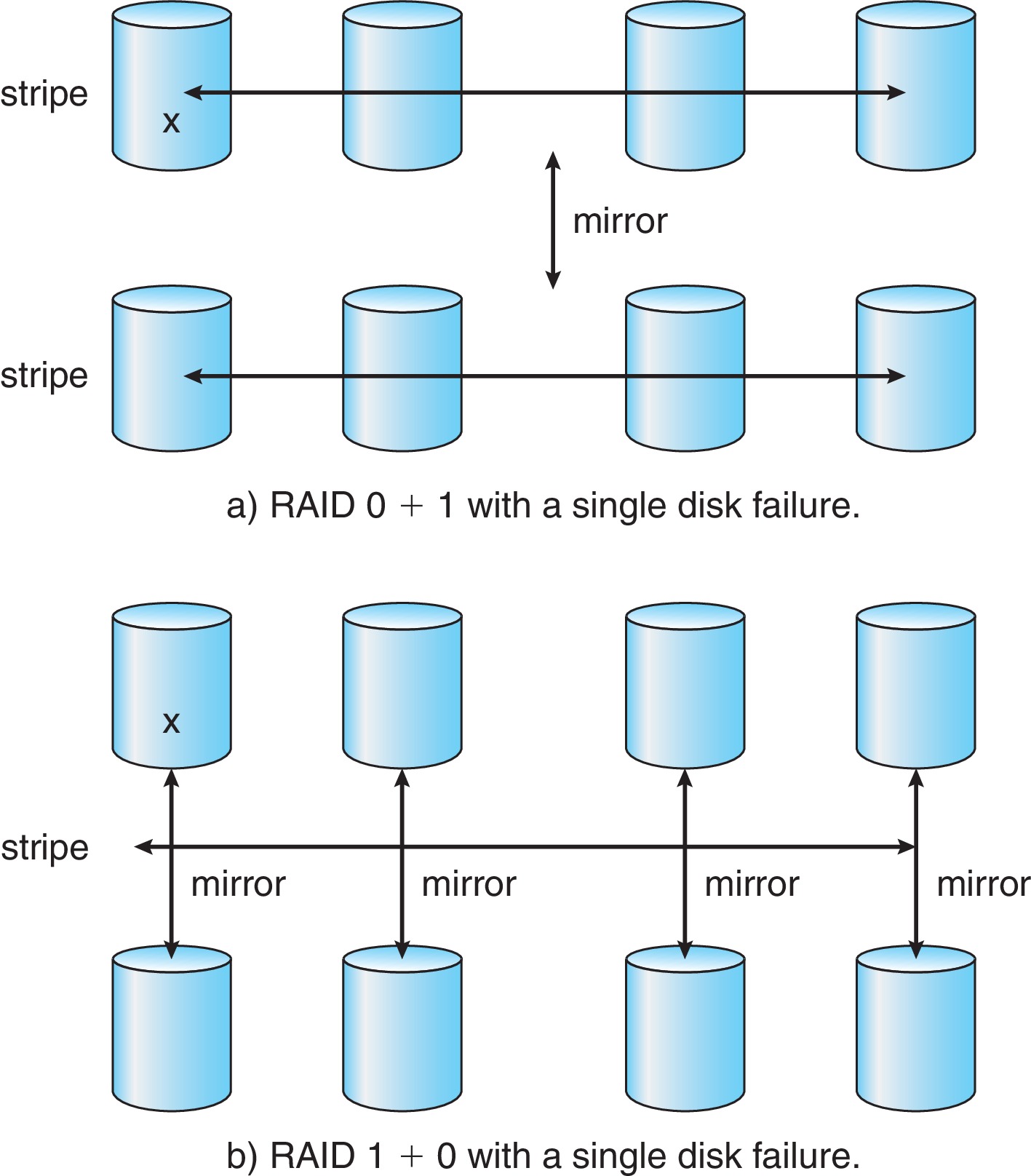
- RAID levels 0 + 1 and 1 + 0
- Rebuild time varies
- Arrays of tapes
- Data broadcasts over wireless systems