(Latest Revision: Tues Jun 04 2019)
[2019/06/04: added captions]
[2019/04/18: first full version]
[2019/04/17: initial spring 2019 updates]
Chapter Nine -- Main Memory -- Lecture Notes
A modern operating system has to make it possible for large numbers
of processes to be in memory at the same time for concurrent
execution. That makes the job of memory management complex.
There is quite a range of options for memory-management algorithms.
Most of these algorithms require special forms of hardware support.
9.0 Objectives
Explain the difference between a logical and a physical address and the role
of the memory management unit (MMU) in translating addresses.
Apply first-, best-, and worst-fit strategies for allocating memory
contiguously.
Explain the distinction between internal and external fragmentation.
Translate logical to physical addresses in a paging system that includes
a translation look-aside buffer (TLB).
Describe hierarchical paging, hashed paging, and inverted page tables.
Describe address translation for IA-32, x86-64, and ARMv8 architectures.
9.1 Background
We assume the primary memory is an array of individually-addressable bytes.
The instruction-execution cycle generates a stream of memory addresses.
The hardware memory management unit (MMU) has no ability
to detect the purpose of an address.
9.1.1 Basic Hardware
The only general-purpose storage that a CPU can access
is primary (main) memory or registers. In
particular, a CPU cannot directly access disk or other peripheral
storage.
CPU access to primary memory is many times slower than access to
registers, but caches help speed things up.
Hardware must provide a mechanism to protect the memory
allocated to each process.
The performance penalty would be very extreme if designers assigned
this task to the operating system - it would simply not be practical.
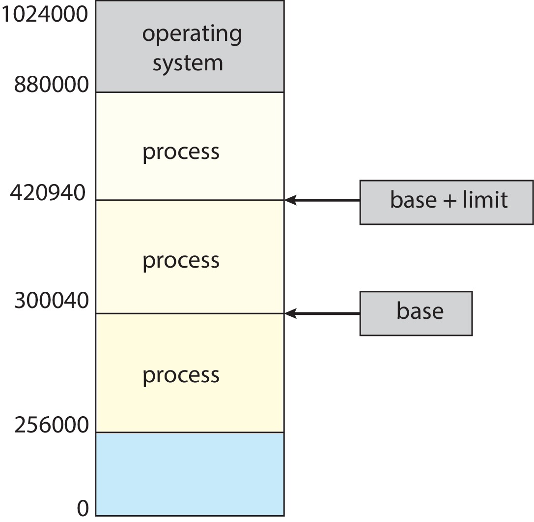
Figure 9.1: A base and a limit register define a logical address space
A simple example of a way to protect memory - with base and limit
registers:
The OS allocates one contiguous span of primary memory
to a process P.
The base register contains the lowest address allocated
to P.
The limit register contains the number of bytes in
the allocation.
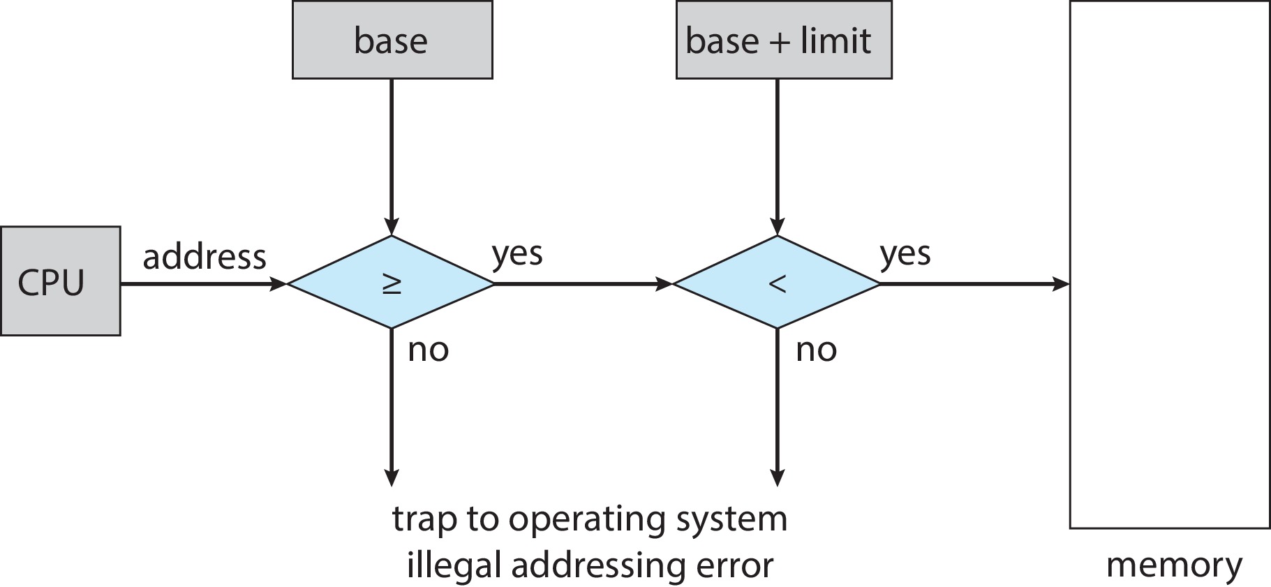
Using the values in the base and limit registers,
hardware checks every address generated
in user mode.
Any attempt in user mode to access memory out of bounds
results in a trap.
Changing base or limit registers are privileged instructions.
The kernel gets unrestricted access to all memory -
a necessity for performing system tasks such as loading
jobs and fetching parameters of system calls.
Figure 9.2: Hardware address protection with base and limit registers
9.1.2 Address Binding
Addresses in the source program are generally symbolic --
e.g. count
Typically the compiler binds symbolic addresses to relocatable,
relative addresses, given as offsets from the base address of
the program or the containing module.
The relative addresses may be converted to absolute
addresses by the linkage editor or loader.
To allow the relocation at run time of programs
from one area of memory to another, contemporary computing
systems utilize special techniques that require
hardware and operating system support.
9.1.3 Logical Versus Physical Address Space
The addresses seen by the CPU are logical addresses, aka
virtual addresses.
The addresses seen by the memory address register (MAR) are
physical addresses, aka hardware addresses
These two address spaces can be identical, but under
execution-time binding (the dominant paradigm), they are
separate.
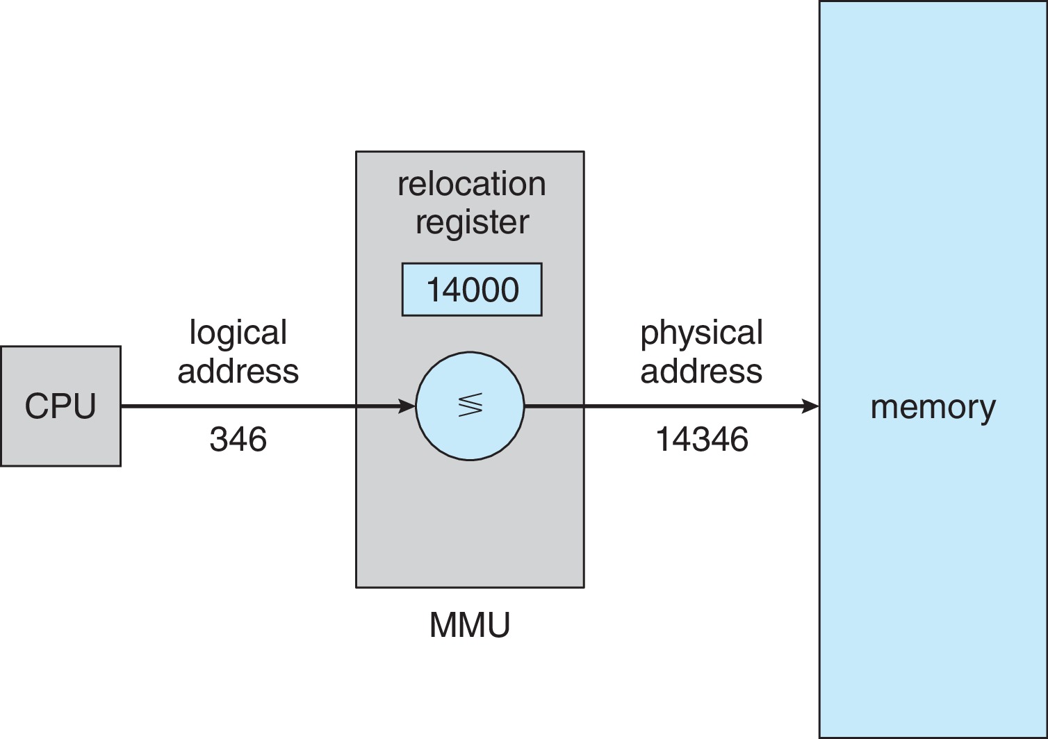
While a process is executing,
the memory management unit (MMU) hardware
is responsible for the mapping from logical address to
physical address required by executing
processes during their fetch/decode/execute cycle.
The user program deals with the logical addresses
exclusively.
The (MMU) hardware translates a logical address only
when a memory access is performed.
Figure 9.5: Dynamic relocation using a relocation register
In a simple example situation, the MMU hardware might
translate logical addresses in the range 0 ... max
to the range R ... R+max, where R is the value
stored in a relocation register, which is similar to
a base register.
9.1.4 Dynamic Loading
Under dynamic loading, a routine is not loaded until it is
called.
Each routine has a disk image represented in a relocatable
load format
Routines that are never called are never loaded. This may
result in considerable savings in memory usage.
Dynamic loading can be implemented just with user processes.
There is no need for any special assistance from hardware or
OS. However the OS may provide library routines that implement
dynamic loading.
9.1.5 Dynamic Linking and Shared Libraries
The in-memory program text originally contains a stub for each
reference that the program has to a library routine. The stub is a
piece of code that tells where in memory or on disk to locate
the library routine.
When the program first executes the stub, the stub
replaces itself with with the address of the routine
and executes it. (If need be, it first loads the routine.)
All processes share the same copy of each library routine.
Because of memory management, user processes need help from the
OS to check on the memory locations of routines.
The sharing of library routines requires help from the
hardware and the OS - shared memory.
9.2 Contiguous Memory Allocation
Contiguous memory allocation was a common memory allocation
scheme used during an earlier time in the evolution of operating
systems. It's a good idea for today's students to learn about contiguous
memory allocation - to get an introduction to the design issues that are
important, and to help the student appreciate the advantages of more
recently developed methods of memory allocation, like paging and
segmentation.
In a contiguous memory allocation set-up, each process resides in
some contiguous address range in memory (e.g. in the L addresses
from base address B to address B+L-1). Typically there are two
partitions in the physical memory, one for the operating system
and one for all the user processes.
9.2.1 Memory Protection
A scheme similar to the base-limit registers idea discussed
in chapter two will suffice to keep track of and enforce
memory allocations.
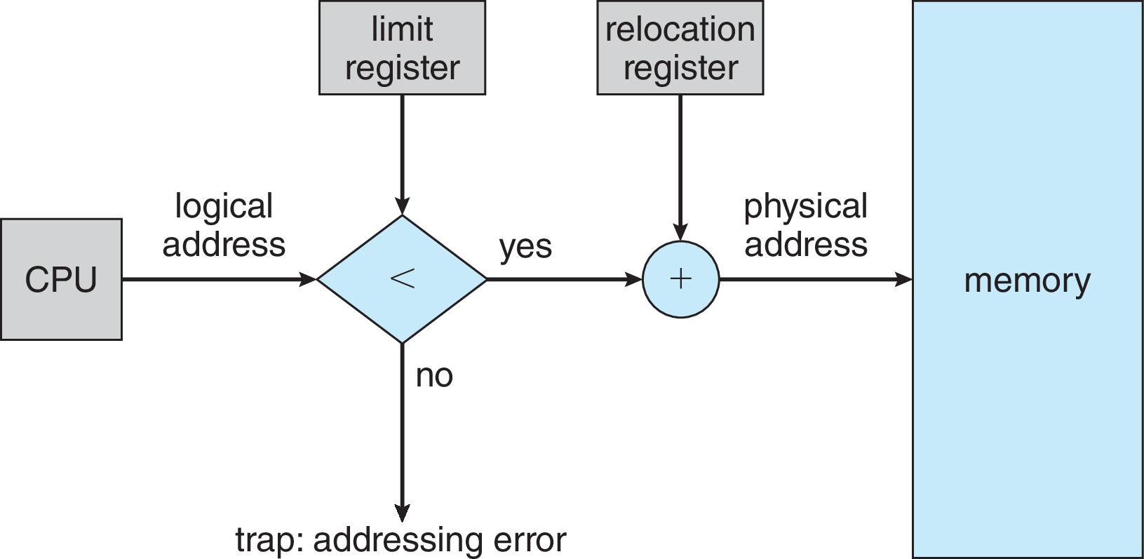
Figure 9.6: Hardware support for relocation and limit registers
In this scheme, there are both logical and physical address
spaces. A user process works with, say, L legal addresses: the
contiguous range from 0 to L-1. The MMU hardware
checks every logical address generated by the user process,
to make sure it is within the legal range. The MMU maps
each legal (aka valid) logical address to a corresponding
physical address by adding the value of the
relocation (aka base) register.
By changing the values of the relocation and limit registers,
the OS can keep track of processes as it relocates and/or
resizes them. The OS can change its own size too.
9.2.2 Memory Allocation
Fixed-size partitioning is a very simple
memory allocation methodology. The OS partitions user
memory into M subsets (partitions) of equal size. Each
partition is a contiguous range of memory. If a process
needs to run, and a partition is available, the OS
allocates one partition to the process. If the
process larger than the partition size, it will be
impossible to run the process. When a process exits,
it releases its partition. The OS puts the partition
on a list of free partitions, to be allocated to another
process later.
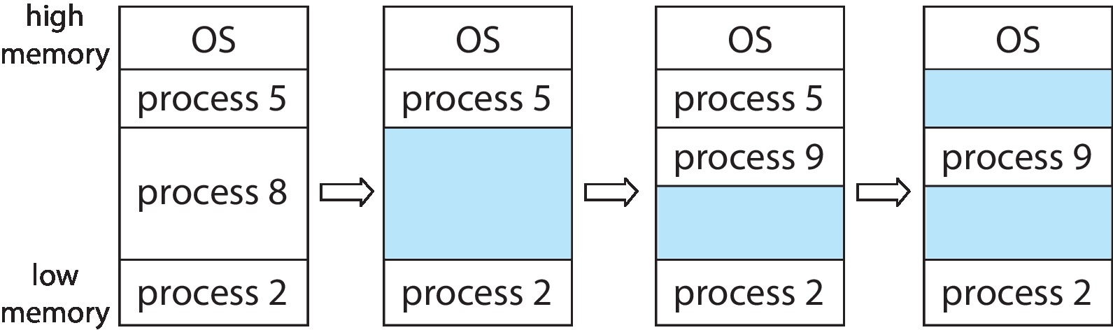
Variable-sized partitioning
is more flexible than fixed-size partitioning.
Figure 9.7: Variable partition
The OS maintains a free-list of available
"holes" in memory.
When a process needs to be loaded into memory, the OS
finds, if possible, a hole in the free-list that
is big enough, removes it from the free-list,
and places the process into an initial contiguous section
of the hole. Any unused remainder of the hole
is a new hole that the OS puts on the free-list.
When a process terminates, it releases its memory
allocation. The OS checks to see if the freed memory can
be merged with adjacent free holes to form a larger free
hole. The resulting hole is inserted into the list.
(Note: holes in the list that are merged with the new hole
have to be deleted from the list.)
The job of allocating the memory under these conditions is
known as the dynamic storage allocation problem:
"... how to satisfy a request of size N from a list of
free holes"
The strategy of searching for a hole may affect
performance. First fit,
best fit, and worst fit are
possibile strategies.
First-Fit: Choose the first hole found that is big enough,
and then stop searching.
Best-Fit: Choose the smallest hole
that is big enough - the one that leaves the smallest
left-over hole. (We can keep the list sorted by size, so we don't
have to search the whole list.)
Worst-Fit: Choose the biggest hole - the one that
leaves the biggest left-over hole. (Here too, we may want to keep
the list sorted by size.)
Some simulations found both first-fit and best-fit to be
faster than worst-fit and able to satisfy more memory requests
than worst-fit. First-fit is considered faster in general than
best-fit. There's no clear winner between first-fit and best-fit
as to which is able to satisfy more memory requests.
9.2.3 Fragmentation
Fragmentation can be external or internal.
External fragmentation is memory that is available but
unusable. (especially a collection of holes, each of
which is too small to use for anything, but which would
be enough to accommodate a process if it were possible to
combine them together into one hole.)
Severe external fragmentation invariably occurs when
contiguous memory is allocated using first fit, best fit, or
worst fit algorithms. For example, 1/3 of the memory
may be wasted (unusable) after a large number of allocations
and deallocations have happened.
Internal fragmentation is memory that
is allocated but not
used. (The allocation method may require that processes
sometimes get more memory than they need. For example,
there may be a
minimum allocation, or allocations may be made in chunks of a
specific size.)
If processes are dynamically relocatable then the OS can move
them around to compact external fragmentation into
usable holes. PROBLEM WITH THIS: it can take a long time if
done all at once, and if tried 'piecemeal' becomes difficult
to do correctly and efficiently.
We will see further along in this chapter that
it is possible to do an "end run"
around the external fragmentation problem by allowing
the memory allocation of a process to consist of
fixed-size, non-contiguous chunks of physical memory
called page frames.
9.3 Paging
The memory allocation method known as paging is an alternative
to contiguous allocation with variable partitioning. With paging, there
is never any external fragmentation at all, and therefore, no need
for compaction.
9.3.1 Basic Method
For purposes of this discussion, let's assume that the
smallest addressable unit of primary memory is a
byte. It should be obvious how to apply the
concepts developed here to situations in which there is a
different word size.
The hardware has a given page size such as 4Kbytes (in other
words, 4096 bytes). We divide primary memory and backing store
into page-sized contiguous chunks (called frames). For
example frame #0 runs from byte #0 through byte #4095; and frame
#1 runs from byte #4096 through byte (4096+4095)=8191.
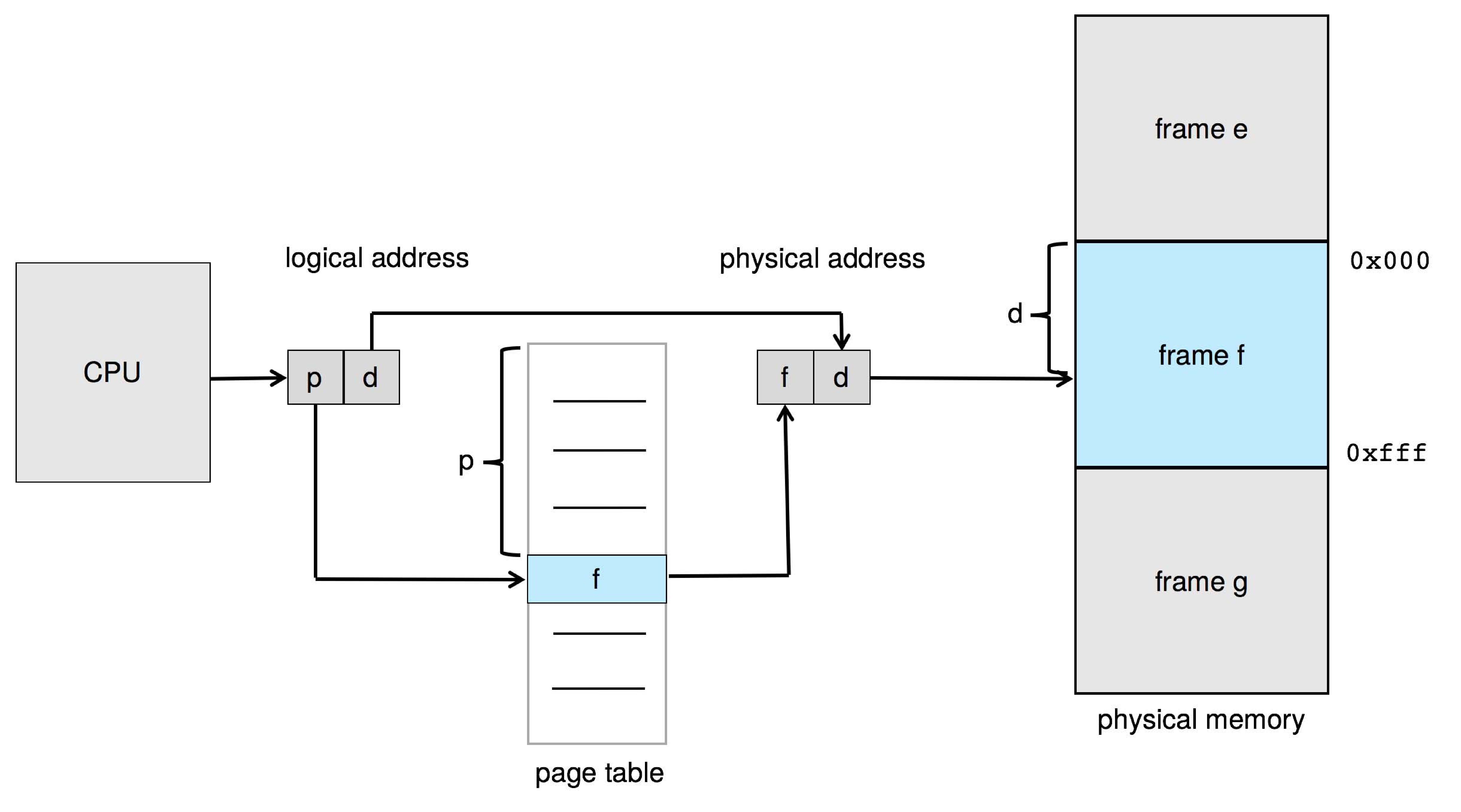
Figure 9.8: Paging hardware
The OS creates a page table entry for each page, when it first
loads the page into a frame. For logical page number i, the OS
puts the number of the frame allocated for page i into entry i
of the process page table. When the process attempts a memory
access, hardware uses some of the most significant bits of the
the logical address (known as the page number) as an index into
the page table. We can visualize the logical address as
( p | d ), where p is the bits of the page
number and d is the remaining bits of the logical address,
called the offset. The hardware finds a
frame numberf at location p in the
page table. To form the physical address, the hardware
constructs ( f | d ) by replacing p in the
logical address with the frame number f.
(The lengths of p and f in bits can be
different.) The hardware then continues with the
memory access.
Suppose that the page size is 2n bytes.
Then each page offset and each frame offset must
consist of n bits.
If the number of bytes of logical memory is
2m, then there are
m-n bits in each page number.
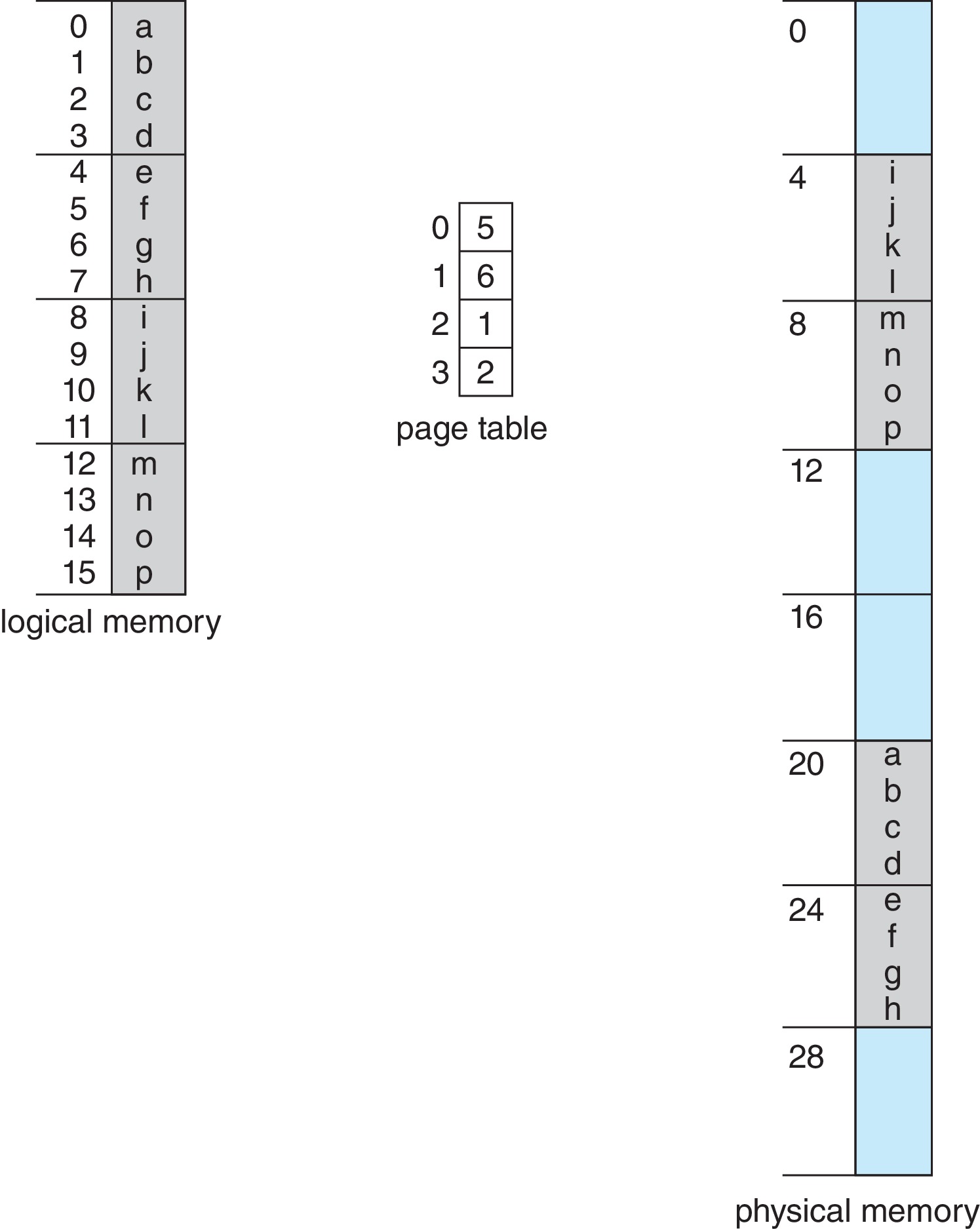
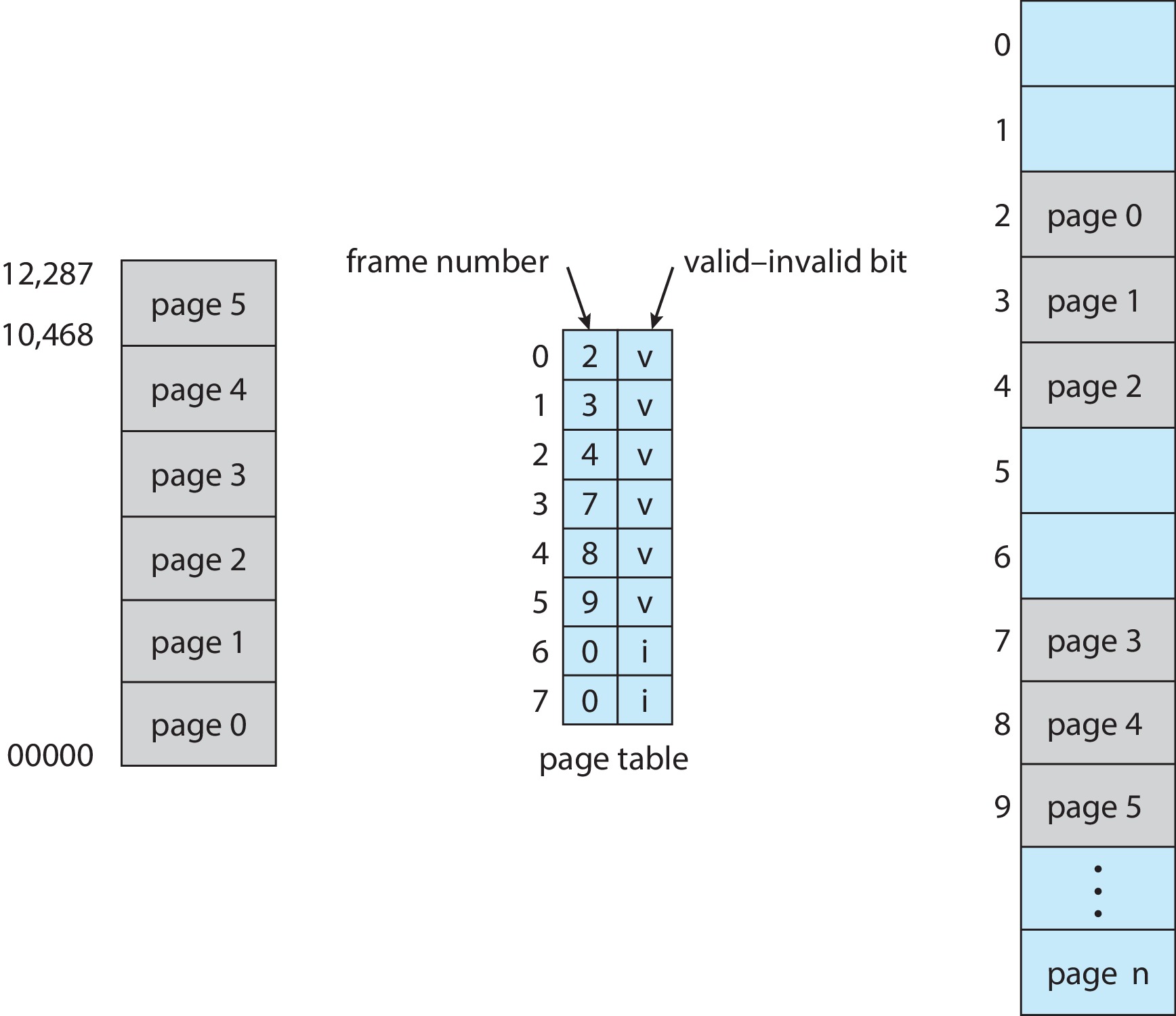
Figure 9.10: Paging example for a 32-byte memory with 4-byte pages
Consider the tiny example above
The page size is 22 = 4,
the size of the logical memory is 24 bytes = 16 bytes, and
the size of the physical memory is 25 bytes = 32 bytes.
The page table maps logical page 0 to physical frame 5, and so on.
An example of address translation: Logical address 13 is
1101 in binary. The offset part is 01 and the page number part is
11, which is 3 in decimal. Using the page number of 3 as index into
the page table, we see that page 3 is mapped to frame 2 = 10 in binary.
So the translation of the logical address to a physical address
is 1001, which is 9 in decimal. We see the 'n' in address 9
of the physical memory.
There is no external fragmentation with paging. However,
typically a process does not need all of the memory in its
"last frame." The remainder is internal fragmentation - about
half a page, on average.
A small page size reduces internal fragmentation. A large
page size keeps the page table smaller and reduces the total
amount of I/O overhead for copying pages to and from the
backing store.
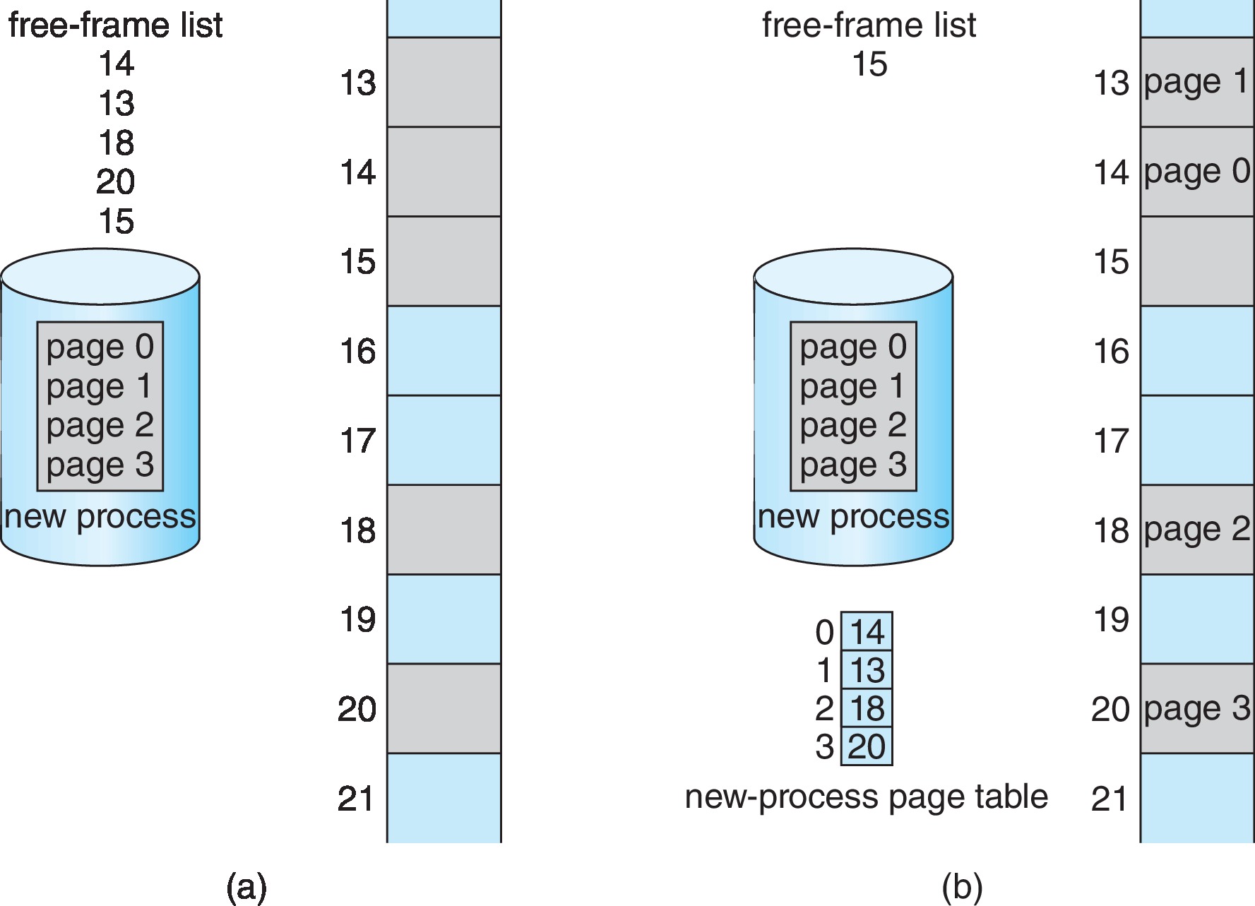
Figure 9.11: Free frames (a) before allocation and (b) after allocation
The figure above illustrates how the OS allocates frames and
creates a page table as it loads a new process.
To put a process into the primary memory, the operating
system writes code and data structures into a set of (physical
memory) frames. The frames don't have to be contiguous
with each other.
However, the logical address space is contiguous.
In effect it is just an array of bytes, ranging from byte #0
to some upper limit.
Memory protection with paging is pretty straightforward. The
OS creates the page table. The OS uses the page table
to protect memory, much as another OS would use base-limit registers.
(The 'bases' are the frame numbers, rather than physical
addresses of memory cells, and the 'limits' are not explicitly
stored, because they're all just equal to the page size.)
A process has no way to address memory outside of its page
table.
The OS has to keep track of all the allocations of the
physical frames. In a system that uses standard paging,
there is usually a frame table data structure that
has an entry for each physical frame. The entry indicates
whether the frame is allocated to a process or not. If it's
an allocated frame, the entry will say to which process(es).
The OS keeps track of a copy of the page table of each process.
Occasionally the operating system will translate a logical
address into a physical address.
Suppose a user process gives an address as a parameter when
communicating with the OS. For example the address could be the
base address of an array that the process wants to use as an
I/O buffer. The process gives the OS a logical address.
(The process only knows about logical addresses.) The
operating system needs to know the physical address.
The OS will use its copy of the page table of the process
to perform this "manual" translation. IMPORTANT: The
hardware, not the operating system, performs the routine
address translation from logical addresses to physical
addresses as a process executes the
fetch-decode-execute cycle in a CPU.
9.3.2 Hardware Support
Page tables can be implemented in a variety of ways.
In an extremely simple case, each process might have its
own page table, and the page table might be implemented using
a bank of dedicated registers. The number of registers
is limited, so larger page tables can not be implemented
this way.
In many contemporary systems, the CPU/MMU architecture
contains a page-table base register (PTBR) pointing to a
large page table that is resident in the main memory.
This has the added advantage of speeding up context
switches, since installing the page table of the new
process just requires changing the value in one register.
A disadvantage of the in-memory page table is that whenever
we use it, two memory accesses are required, one
to look up the frame number in the page table, and then a
second to actually fetch or store the desired data.
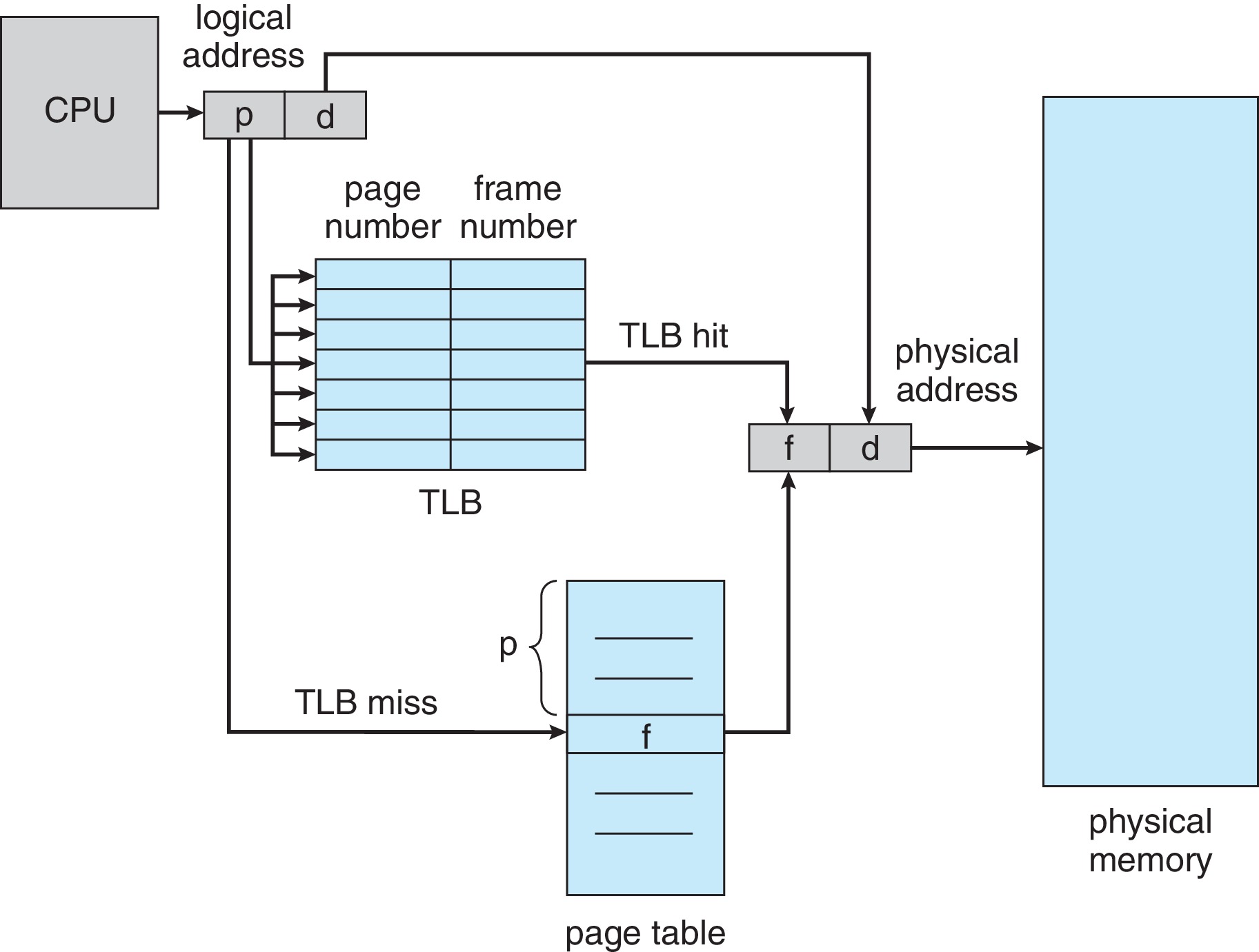
9.3.2.1 Translation Look-Aside Buffer
To avoid slowing memory access by a factor of two, contemporary
systems use a fast associative-memory address cache
(a translation look-aside buffer - TLB) so that the
MMU does not usually have to take the time to access the page
table when performing an address translation.
Figure 9.12: Paging hardware with TLB
The hardware checks the TLB first for the the address translation.
If there's a miss, the page table is consulted and the information
found is inserted in the TLB for future use. If the TLB was full,
this means an existing entry was overwritten.
At this point, whether there was a TLB hit or miss, the MMU has
now placed the needed physical address in the memory address register,
and the access to the physical memory proceeds.
When it is necessary to access the page table in memory, depending
on the particulars of the system design, it could be either the
hardware or an OS interrupt routine that performs that access.
Address Space Identifier (ASID) technology allows the TLB to
contain address translation information for several different
processes.
ASID technology also cuts down on the necessity to do
time-consuming cache flushes during a context switch.
Effective memory access time (EAT) is a function of the hit ratio,
memory access time, and TLB search time. For example, if
the hit ratio is 90% and the memory access time is 12 nanoseconds,
then, according to our simple model, the EAT would be
calculated as (0.9)(12)+(0.1)(24) = 13.2 ns.
9.3.3 Protection
Some bits in page table entries (PTEs) can be used to
make access restrictions on pages - a read-only bit,
for example. The hardware can be designed to generate
a trap if a user process attempts to write to a
read-only page. It is also common for a PTE to contain
a valid bit.
Some systems make the page table only as long as is necessary
for the size of the process. Such a system would typically
have a page-table length register (PTLR). A process attempting
to access an address "past the end of the table" would generate
a trap to the OS.
In any case, the valid bit in "extra" page table entries can be
cleared by the OS so that the process will trap if it tries to
use one of those entries.
Figure 9.13: Valid (v) or invalid (i) bit in a page table
Unfortunately a process generally can access the
internal fragment in its last page.
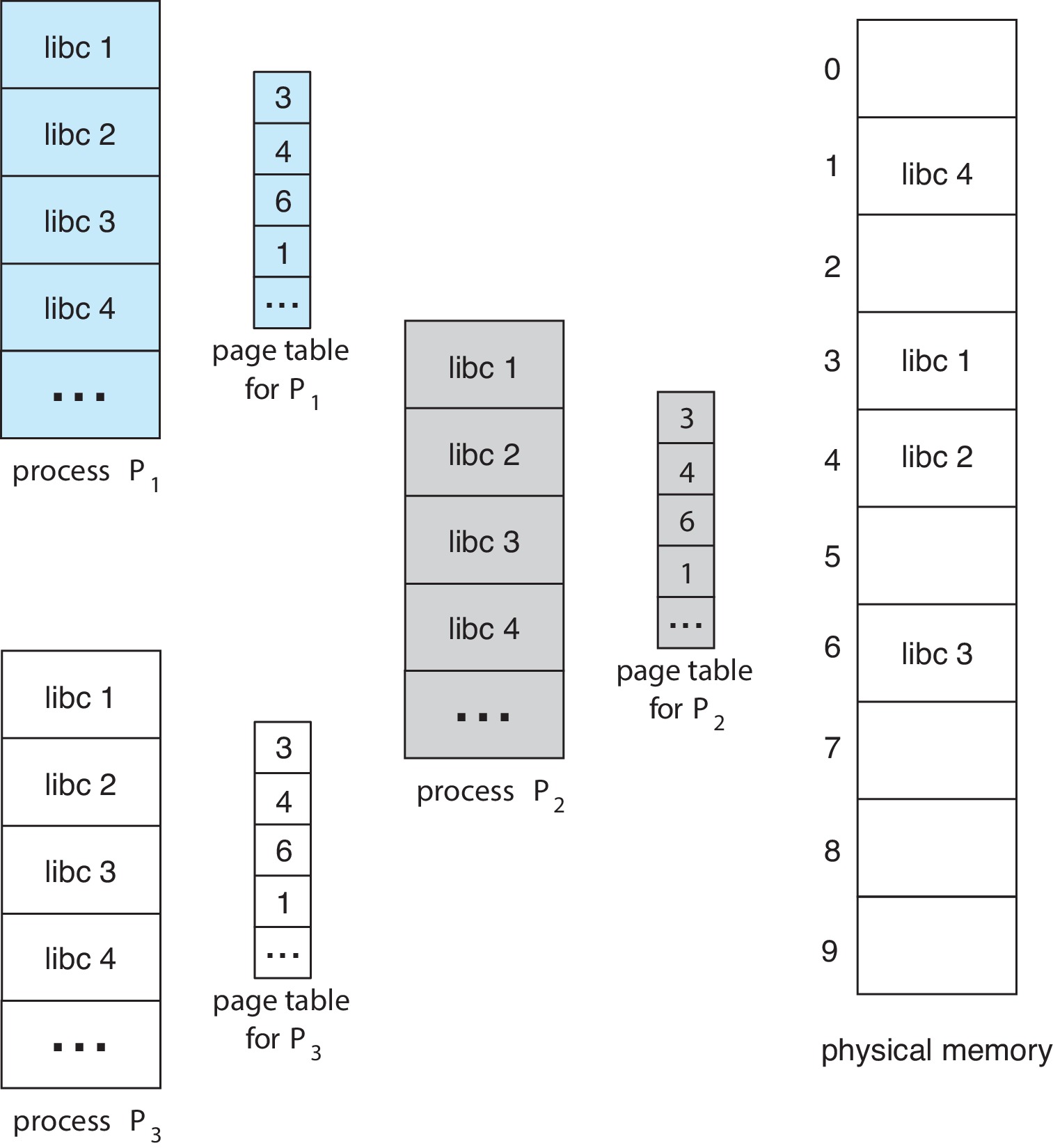
9.3.4 Shared Pages
The paging paradigm easily supports shared memory (at least
when "traditional" hierarchical page tables are used.)
If two processes have the same frame number in both their
page tables then they are able to share that frame.
Figure 9.14: Sharing of standard C library in a paging environment
The OS can use this idea to allow many processes to share
the same read-only program text.
Writeable memory may be shared as a means of interprocess
communication.
9.4 Structure of the Page Table
9.4.1 Hierarchical Paging
A common size for page table entries (PTEs) is 4 bytes.
212 bytes = 4KB is a typical page size.
Assuming the sizes above, a page of 4KB has room for
210 PTEs = 1024 page table entries.
Assuming a logical address space that uses 32-bit addresses,
there are 232 addressable bytes. If the page size
is 212 bytes, then 20=32-12 of the bits in an
address comprise the page number, which implies
there can be as many as 220 pages in the logical
address space of a process. That is about a million pages.
Again, under the assumptions above, the page table for a
process with 220 pages would contain
222 bytes, which is 210*212 bytes.
Therefore the page table itself would span 210=1024 pages.
To avoid having to solve an instance of the dynamic storage
allocation problem for page table allocation,
it may be workable to page the page tables instead
- at least when they are significantly larger than one page
in size, and also when they are not too big.
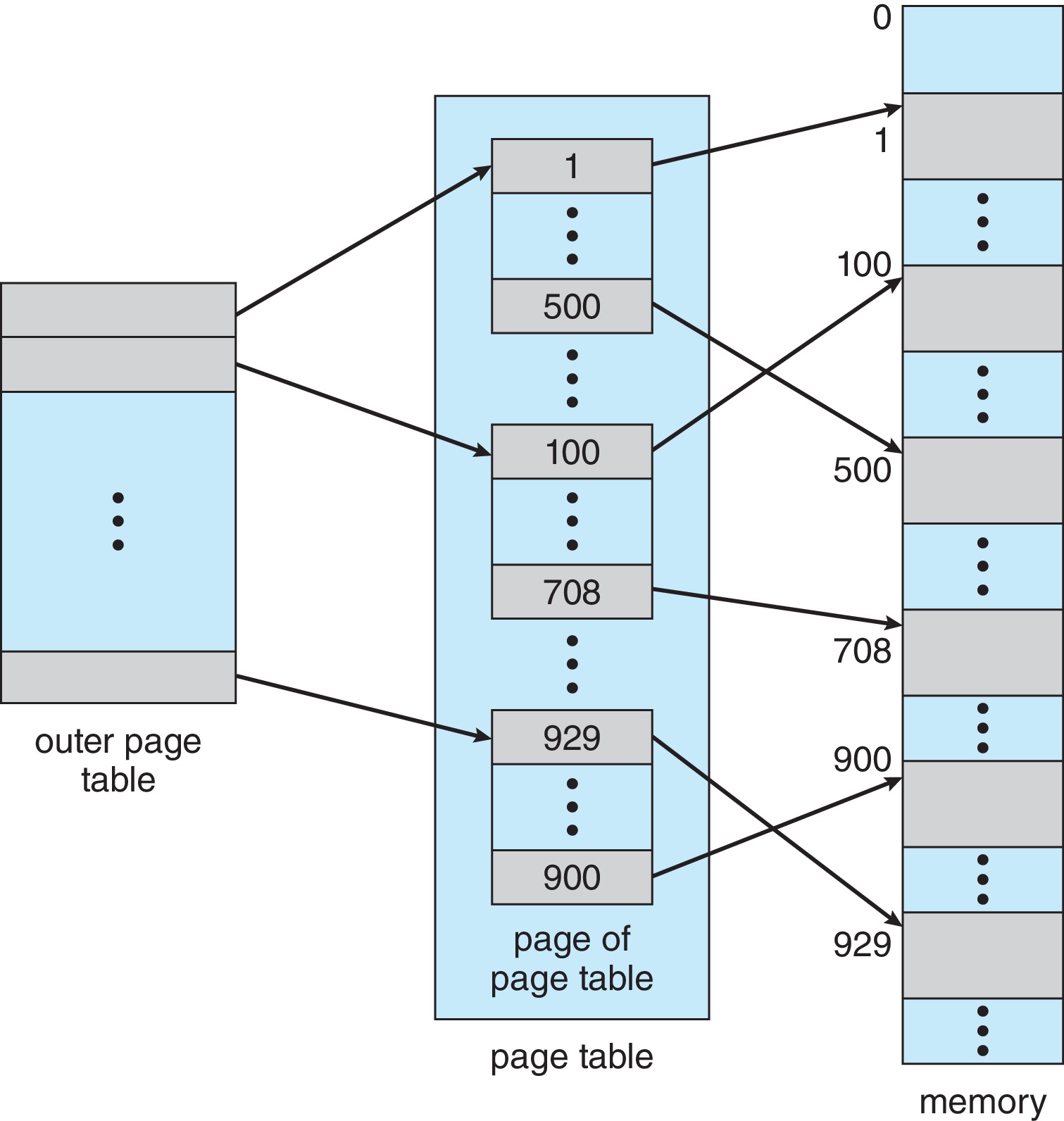
Figure 9.15: A two-level page-table scheme
In one scheme, the logical address is partitioned as
(P1 | P2 | d). P1 is used as an index
into an outer page table. The entry in the outer
page table is the frame number of one of the pages of the
page table. P2 and d are then used in the
"normal way" to complete the address translation: P2
is used as an index into the specific page of the page table.
The frame number found in the PTE is combined with d
in the usual way to form the physical address.
For still larger page tables, some architectures have supported
more levels of paging, where, for example, not only is the page
table paged, but so is the outer page table.
One of the SPARCs produced by Sun Microsystems
supported three-level paging, and the Motorola 68030 had
support for four-level paging.
Generally it is not considered appropriate to map a 64-bit
paged address space with this type of 'traditional' hierarchical page
table. It requires what is considered an excessive number of
levels of page tables -- e.g. seven levels.
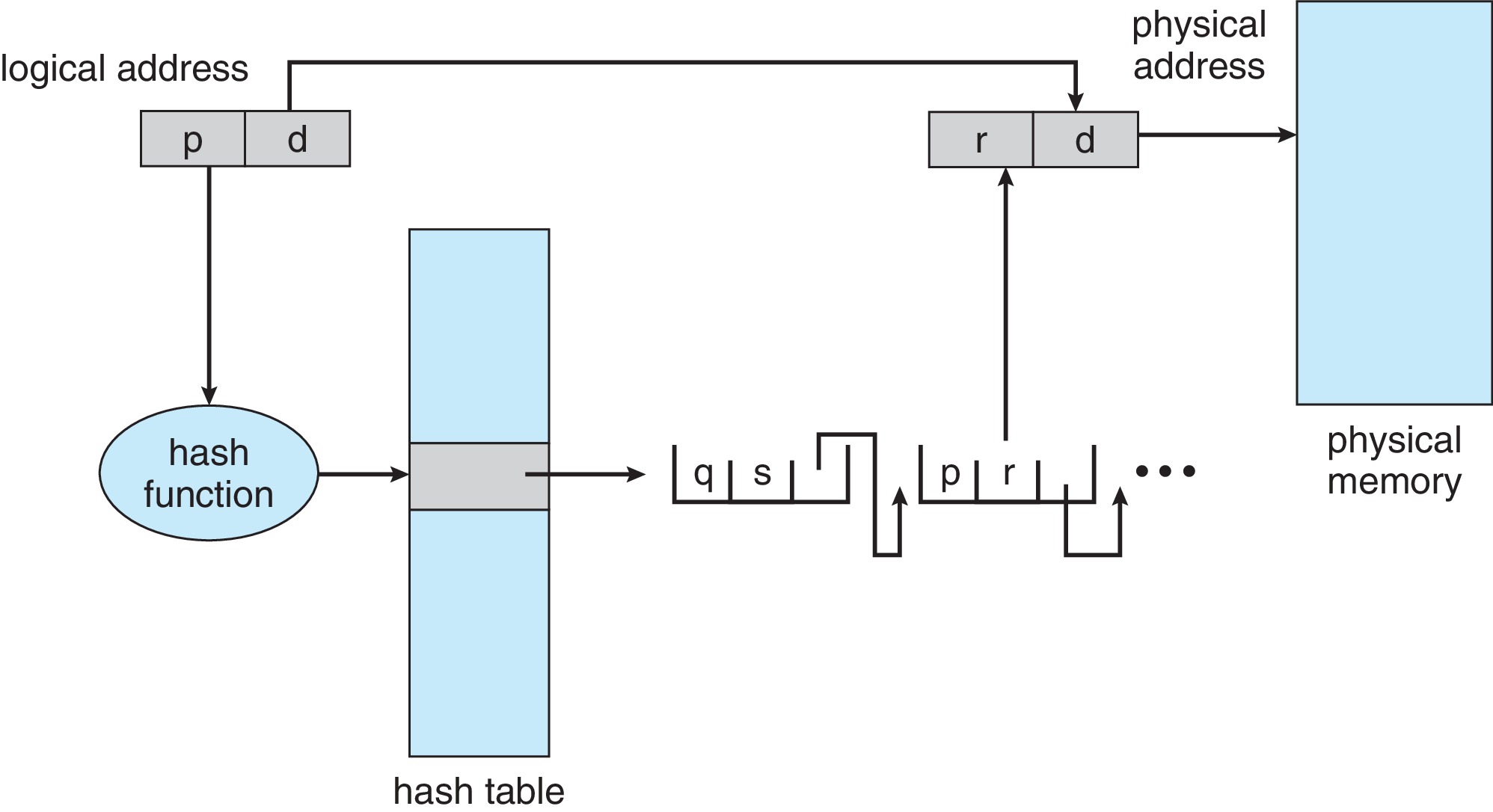
9.4.2 Hashed Page Tables
Per-process hashed page tables are an alternative to
hierarchical page tables. A hash function is applied to the
virtual address. Collisions are resolved with external
chaining. Each entry on a chain contains a virtual address,
frame number, and pointer for the next item on the chain.
Figure 9.17: Hashed page table
Clustered page tables are a variant in which each entry in the
page table refers to several pages.
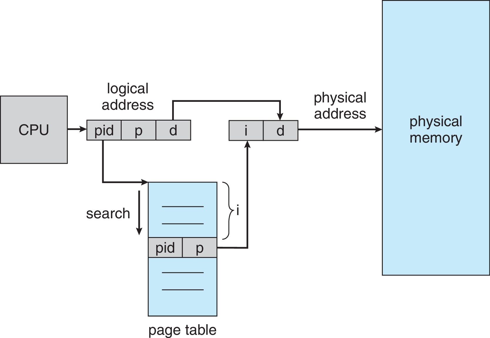
9.4.3 Inverted Page Tables
Some systems, including the UltraSPARC and PowerPC, utilize
an innovation called an inverted page table. An
inverted page table has one entry for each frame.
The entry identifies which "address space" (e.g. which process)
is using the frame, and for which virtual page number the frame
is being used.
Figure 9.18: Inverted page table
There is just one inverted page table for the whole system,
not one page table per process. A distinct advantage of the
methodology is that the amount of memory used by the
inverted page table is bounded by a constant times
the amount of physical memory, as opposed to
being bounded only by the number of processes and the
max size of a virtual address space.
A distinct disadvantage of using inverted page tables is
that the hardware and/or the OS cannot directly index into
the table using the page number, so it could take a long
time to search this table to find the information
needed for a forward address translation. (On the other hand
this structure easily supports efficient reverse
address translation.)
The idea of a hashed page table may be used in conjunction with
the inverted page table to speed the search for the correct
table entry. A hash function can be applied to the address
space identifier and virtual address to determine the location
to perform an initial probe. External chains can provide
subsequent locations to probe until the matching entry is
found.
Of course if there is a cache hit in the TLB, the page table is
not consulted and effective memory access time is nearly
equal to memory access time. If there is a TLB miss and the
page table is consulted, then (forward) address translation
requires additional memory accesses
for operations on the page table and hash structure.
If entries in the inverted page table are allowed to contain
only one virtual page number, it becomes difficult to implement
shared memory. If we provide information for more than one
process and virtual page number in an inverted page table entry,
then the amount of memory used by the page table can no longer
be said to be
big-O of the size of physical memory.
9.4.4 Oracle SPARC Solaris
This system utilizes two hash tables for forward address
translation, one for the kernel, and one for all user
processes. Rather than have a separate entry for each page,
each entry of the hash table represents a contiguous span of
mapped virtual memory.
The system utilizes a TLB, and an in-memory cache of translation
table entries (TTEs) that plays the part of a level-two TTE cache.
9.5 Swapping
9.5.1 Standard Swapping
The idea of swapping is to temporarily take away main memory
from one process in order to give it to another process.
If we take away memory from process X, we need to be able
to restore X later, so we first copy the contents of X's
memory to secondary storage, and then give the memory to
one or more other processes. We say X has been
swapped out.
When we copy X to secondary storage, we copy the
text and data of X, and much of the context information about
X. The operating system has to retain enough information
about X to be able to find X later and copy it back into memory
(swap it in) to resume its execution.
An operating system that can perform swapping can multiprogram
more processes than will actually fit into the physical memory
all at once.
Processes that have been idle for a long time are good candidates
for being swapped out.
9.5.2 Swapping with Paging
It is not practical in modern systems to perform standard
swapping because it takes too long to swap whole processes
in and out.
It is much more common to perform paging
to swap in and out individual pages of a process.
In a system that performs paging, it is very unlikely that
more than a small proportion of the pages of any process
will be swapped out at any time.
9.5.3 Swapping on Mobile Systems
Mobile systems don't typically perform swapping, because
Swapping requires large amounts of secondary storage, and
mobile systems lack that.
Throughput between main memory and secondary (flash) memory
is slow.
Swapping would tend to quickly use up the limited number
of write operations that secondary flash memory can support.
Instead of swapping, iOS asks applications to relinquish unneeded
memory, and iOS may terminate processes that don't free up enough
memory.
Android acts in a manner similar to iOS, except before killing a
process for overuse of memory, it will save its state on secondary
memory so the application can be restarted quickly.
Because of the conditions described above, programmers
for mobile environments have to incorporate conservation-minded
memory allocation/deallocation procedures in the applications
they write.
9.6 Example: Intel 32- and 64-bit Architectures
Popular PC operating systems run on Intel chips, including
Windows, macOS, and Linux. Linux runs on other
architectures besides Intel.
Advanced RISC Machine (ARM) architecture is popular for mobile
devices.
9.6.1 IA-32 Architecture
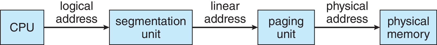
The Intel IA-32 system has a combined segmentation and paging
scheme.
Figure 9.21: Logical to physical address translation in IA-32
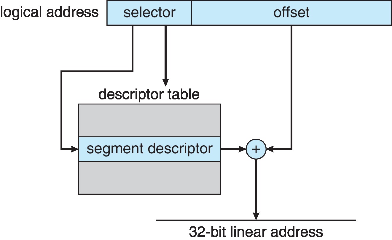
9.6.1.1 IA-32 Segmentation
Logical addresses consist of a (selector, offset) pair
that is very similar in purpose to the kinds of addresses
used in pure segmentation, which consist of a segment
name (number) and an offset within the segment. (Segments
are chunks of contiguous memory specified with a base
address and a limit. A process can be assigned many
different segments.)
There is a segmentation unit, in effect a part of the
MMU, that uses a data structure much like a segment
table to translate a logical address into an
intermediary form called a linear address.
This is done by adding the offset to the base
address of the segment.
(If the offset is not less than the limit,
a trap results.)
Figure 9.22: IA-32 segmentation
9.6.1.2 IA-32 Paging
In effect, the IA-32 segments are paged, so the
next step in finding the physical address is to
determine which (logical) page of the segment is referenced
by the linear address, and to locate the physical
frame to which that logical page is mapped.
There is a paging unit, also in effect part of the
MMU, which translates the linear address into a
physical address.
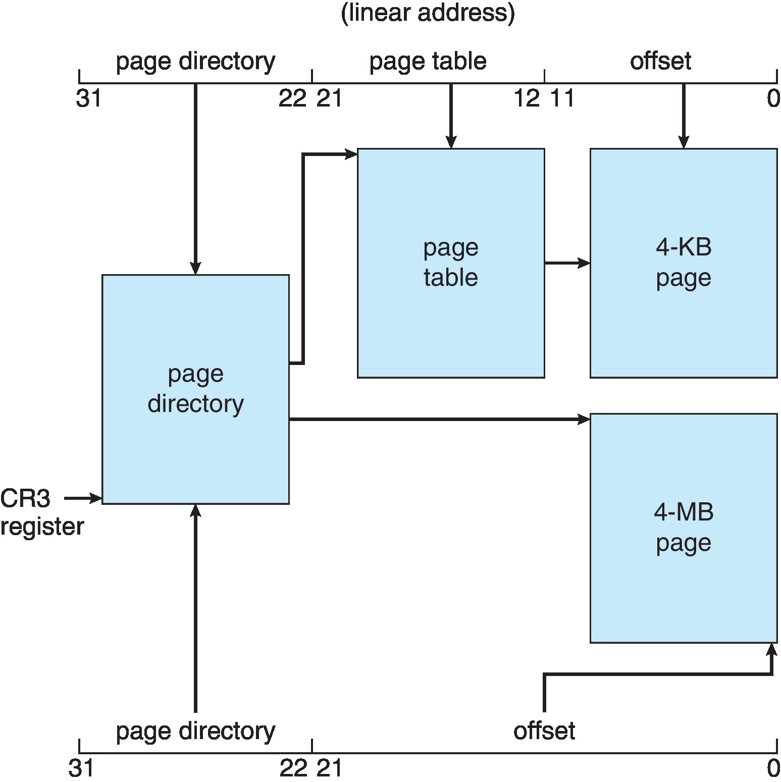
There are two page sizes supported by the IA-32, 4KB and
4MB. A Page Size Flag in the outer page table
is set if the page size is 4MB.
If the flag is not set, then the paging unit carries out
a standard two-level forward address translation procedure
to form the physical address.
If the flag is set, then the paging unit carries out
a standard single-level forward address translation process,
using the outer page
table alone, and bypassing the step of going to the inner
page table.
Figure 9.23: Paging in the IA-32 architecture
The IA-32 system employs virtual memory techniques, allowing
parts of page tables to not be resident in primary memory.
The OS can bring them into memory from disk when they
are needed.
9.6.2 x86-64
The x86-64 architecture, developed by Advanced Micro Devices (AMD)
and adopted by Intel, can potentially support 64-bit address spaces.
Current systems are using the architecture to support up to
48-bit virtual addresses and up to 52-bit physical addresses.
9.7 Example: ARMv8 Architecture
ARM architecture is used in many mobile devices.
ARM architecture can support 4KB, 16KB, or 64 KB pages.
ARM architecture can support sections of contiguous memory
(regions) of size 2MB, 1GB, 32MB, and 512MB.
The ARM architecture supports two levels of TLB, with separate inner
(micro) TLBs for instructions and data.
The inner (micro) TLBs support ASIDs
If there is a miss in the inner TLB, an outer main TLB is consulted.
If page table "walks" are required because of misses at both
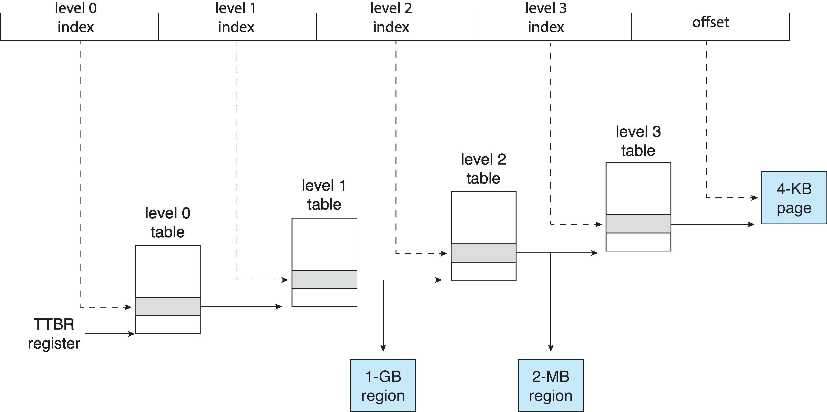
levels of TLB, the ARM hardware performs them.
Figure 9.27: ARM four-level hierarchical paging